6 18-HE46D1-3
Installer’s Guide
SYSTEM SETUP
10. The control board contains a momentary test switch (S1)
and a 4-position installer selectable dip switch (S2).
Both components are located in the lower right hand
corner of the control board. See Figure 8.
TEST SWITCH
The test switch provides a means of verifying that the fan
motor is under the control of the Low Ambient Controller. A
“Y” signal must be present in order to test the control.
Depressing the test switch causes the fan to alternately cycle
on (for 3 seconds) and off (for 3 seconds) for a total time of
12 seconds. The on/off fan operation may be observed by
watching the fan once the test function has been invoked or
by monitoring the head pressure using a gauge set. The LED
on the solid state relay should light when voltage is being
applied to the fan motor. Once the 12-second test period is
complete the control resumes normal control operation.
DIP SWITCHES
The controller will control to a liquid temperature set point
as determined by the dip switch settings. The dip switch is
used:
1. To select either Automatic Mode or Manual Mode
operation (S2 dip switch 4 setting).
2. To select the liquid temperature set point (S2 dip switch
1, 2 and 3 settings).
Automatic Mode (S2 dip switch 4 in “Off” position) –
The controller determines the approach temperature
based upon the liquid and ambient temperature read-
ings. The approach temperature = liquid temperature –
ambient temperature. The approach temperature is
calculated only when the ambient temperature is in the
range of 65 to 75 deg. F. and the outdoor fan is on
continuously. If the controller has not yet acquired an
approach temperature, S2 dip switch 1, 2 & 3 settings
are used for determining the liquid temperature set
point the same as in Manual Mode. If the controller has
acquired an approach temperature, then the liquid
temperature set point is determined as follows:
Liquid Temperature Set Point =
Approach Temperature + 70 deg. F.
Manual Mode (S2 dip switch 4 in “On” position) –
The S2 dip switch 1, 2, 3 settings are read by the
controller and used to determine the liquid temperature
set point when
1. Y is first applied
2. and after initial start-up mode completion, i.e., during
the system control mode (no sooner than six minutes
after Y is applied). The liquid temperature set point
will not change during system start-up.
The dip switches should be set prior to initial application
of the Y signal to the controller.
The dip switches should be set for each specific HVAC
system based upon the following instructions:
Determine Liquid Temperature Set Point
Reference appropriate high side charging chart for the
unit; liquid pressure for cooling units and head pressure
for heat pump units.
Locate the high side pressure for 70 deg. F. outdoor
temperature at the expected indoor wet bulb tempera-
ture. Correct the high side pressure according to the
specific indoor unit being used. For Heat pumps
subtract 7 psi, for cooling only units subtract zero psi.
Using the refrigerant properties chart, find the satura-
tion temperature for the calculated liquid pressure.
Subtract the anticipated sub-cooling temperature
(typically 12 degrees) from the saturation temperature to
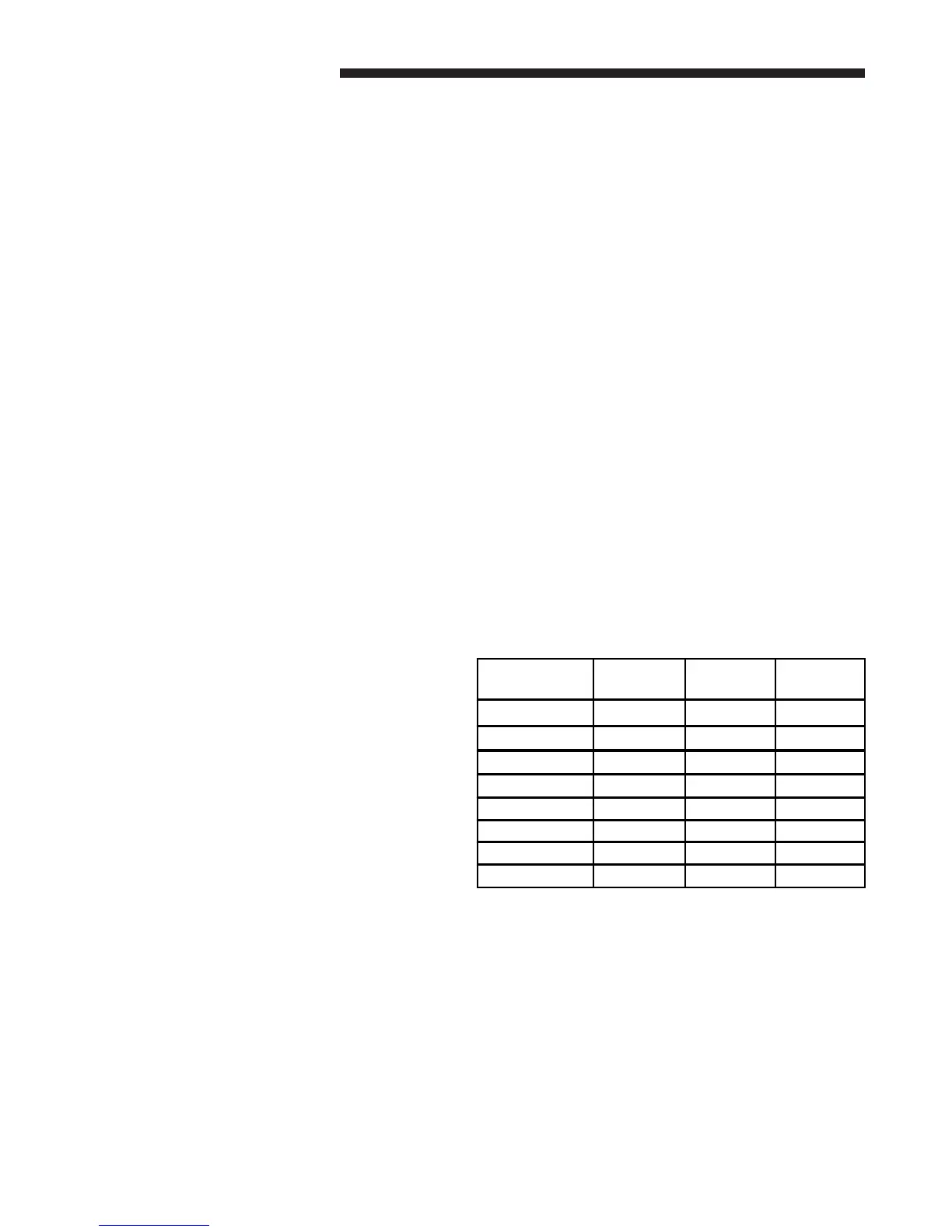
obtain an estimate of the liquid temperature. Set S2 dip
switch 1, 2 and 3 settings to the nearest liquid tempera-
ture set point in the table below.
S2 Dip Switch 4; Off – Automatic Mode
(recommended setting)
On – Manual Mode
LIQUID TEMP
SET POINT°F
DIP
SWITCH 1
DIP
SWITCH 2
DIP
SWITCH 3
70 °F OFF OFF OFF
76 °F OFF OFF ON
82 °F OFF ON OFF
88 °F OFF ON ON
94 °F ON OFF OFF
100 °F ON OFF ON
106 °F ON ON OFF
112 °F ON ON ON
 Loading...