34 CLCH-SVX07C-EN
Installation - Mechanical
5. Use a bar clamp to pull adjacent shipping section lifting lugs together.
7. Verify that the subassembly with the overhang profile on the roof is higher than the mating
subassembly. If it is not, raise one end of the subassembly and bring the unit together. See
Figure 21. In addition, an adjustment can also be made to the height of the roof of either
subassembly by loosening the screws in the vertical channels or component structure and
adjust the height of the roof (see Figure 22 and Figure 23).
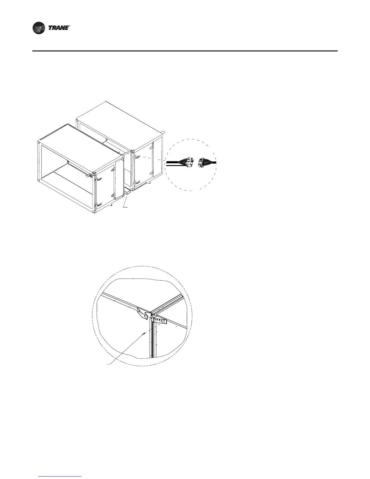
Figure 19. Horizontal section-to-section quick connects 4. If the unit is equipped with factory-
mounted controls, move adjacent
subassembly within six inches and fasten
quick connects where the sections bolt
together (see Figure 19).
Note: Reference the appropriate controller
manual for more details on the
installation of units with factory-
mounted controls.
Use 2 x 4 inch wood to protect
hands from accidental pinching
Figure 20. Wedge block attachment 6. For indoor units sizes 66-120 and for outdoor units
size 10-120, a wedge block is provided to aid in
pulling and aligning the units together. Attach the
wedge blocks to both sides of the units being
pulled together, matching the correct wedge block
with the correct hole pattern. See Figure 20.
Screw
0.250-14 x 0.75
Leached self-driller
 Loading...