12 BAS-SVX51L-EN
Best Practices
• Tape back the shield at each of the Tracer
®
BACnet
®
terminators to prevent accidental contact with
metal components.
Note: If a Tracer
®
UC400 is at the end of the link, the process is the same. The Tracer
®
SC+ provides
the ground wherever it resides on the link.
• During installation, compile a set of as-built drawings or a map of the communication wire layout.
Sketches of the communication layout should feature the Tracer
®
BACnet
®
terminators.
• The Tracer
®
BACnet
®
Terminator is a powered device and it will not work without a power source.
Connect TBT power terminals to a 24 Vac/Vdc power supply.
Note: Some third-party devices have a network terminator built into the device. The use of the terminator
is usually controlled by a jumper or switch on the device itself. Verify that the terminators on each
device are disabled, so that only the TBT are biasing the network.
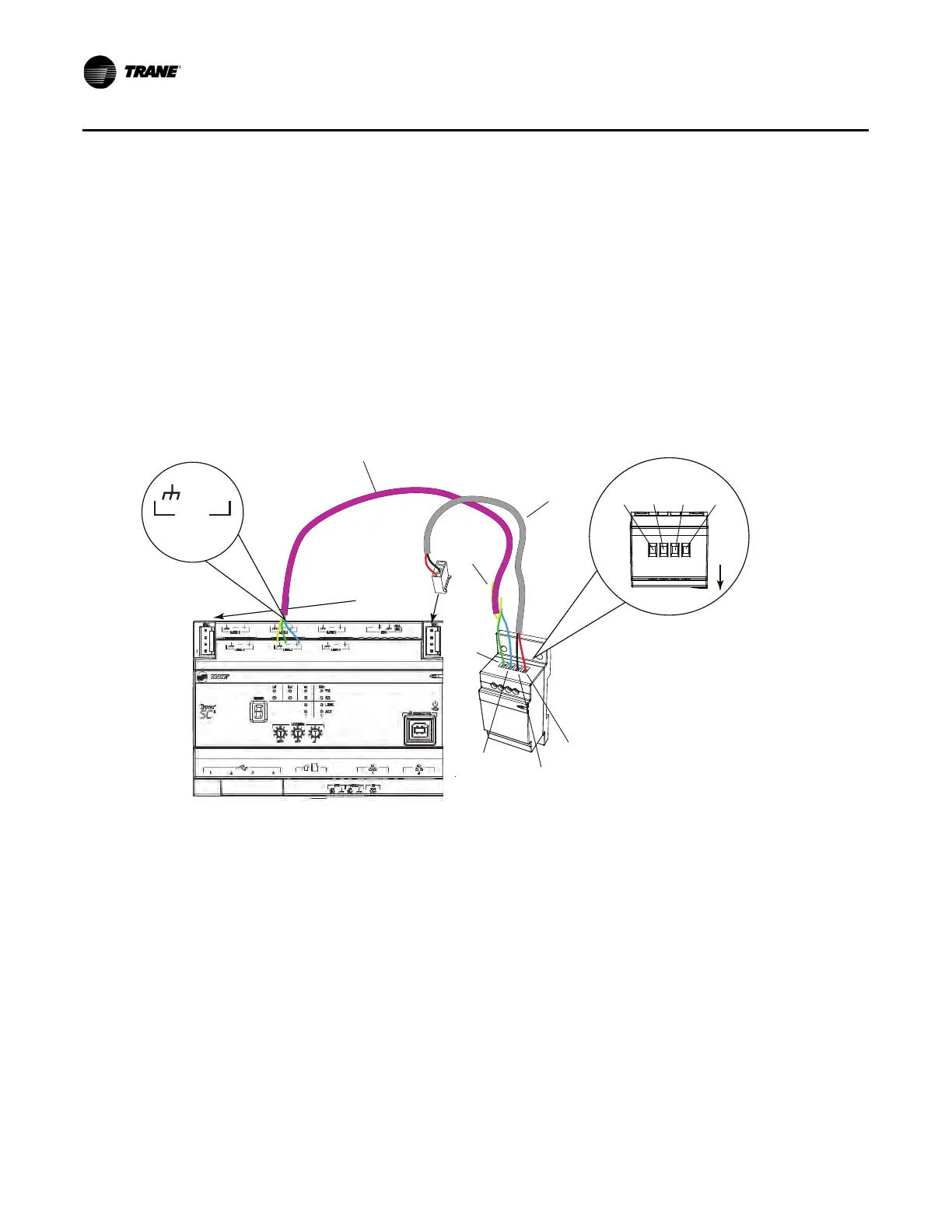
Figure 7. Terminating BACnet
®
links using BACnet
®
terminators
Use the built-in terminator on the BCI-R when the BCI-R is the last node in the network.
The Trane BCI-R has a built in BACnet
®
terminator. If a BCI-R is the last node on the network, this
terminator should be installed as shown in the BCI-R installation guide (RF-SVN03*-EN). For other BCI-
R devices that are not the last node on the link, verify that the terminator has not been wired to the network.
Note: The new BCI2-R does not have a built in terminator. If a new BCI2-R is the last node on the link,
an external BACnet
®
terminator must be added.
BACnet-
BACnet+
Tracer SC+
BACnet
Terminator
Ground
(black wire)
Power
(included
with TBT)
Comm (field-supplied)
24 Vac/Vdc
(red wire)
Cut and tape
back the
shield wire
BACnet-
BACnet+
Ground
24Vac/Vdc
Front
BACnet Link
(maintain polarity)
Use either IMC
connection
LINK 2
Use either Link 1
or Link 2
+
–