BAS-SVX51L-EN 9
Best Practices
Network Wiring Configurations
To Ensure proper network communication, the selection of the appropriate cable and length limitations
must be considered. The following figures describe network wiring configurations that are acceptable,
depending on the type and number of devices that are being connected together on an MS/TP link.
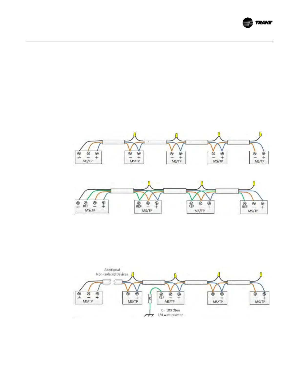
Do not mix isolated and non-isolated device types on a single link.
Trane recommends that isolated and non-isolated device types are not mixed on a single link. Run
separate 2-wire and 3-wire MS/TP links. Figure 1 and Figure 2 describe the correct method to wire each
network type.
Note: End of link terminators have been omitted from the drawings. End of link terminators are required.
Figure 1. 2-Wire MS/TP network
Figure 2. 3-Wire MS/TP network
2-Wire Mixed Device Networks
There are cases where it is not practical to separate isolated and non isolated devices to separate links.
Typical cases include retrofit or system expansion applications where existing wiring will be used. Figure 3
describes the method for connecting one isolated device to a 2-wire link. Figure 4, p. 10 describes the
method for connecting two or more isolated devices to a 2-wire link.
Figure 3. 2-Wire network with isolated device