BAS-SVX51L-EN 40
Troubleshooting Options
Troubleshooting Technique (Isolation)
Physical problems require some trial and error monitoring at various points on the link to isolate the
location of the problem. Use this procedure, your volt meter, and Table 8, p. 41 to help you find the
problem.
Important: Before troubleshooting the link, locate a valid set of prints for the project that show how the
devices are wired on the link along with their addresses.
The following steps define the isolation technique for troubleshooting BACnet
®
links.
1. From the Tracer
®
SC+, verify the following:
a. The SC is grounded properly.
b. Rotary address setting on the SC.
Note: Ensure that the rotary switches match the submittal documents. If you change the rotary
switches, verify the Tracer
®
SC+ BACnet
®
configuration by navigating to (Installation >
Identification and Communication > BACnet
®
Configuration) at the Tracer
Synchrony user interface.
c. Shield wires are properly terminated.
d. Communication wiring terminal is fully seated on the controller.
e. Polarity of the comm link is maintained.
f. Both the in and out wires are properly terminated (tug test each).
2. Verify that a Tracer
®
BACnet
®
Terminator is properly installed on each end of the comm link.
3. Go to the device in the middle of the link and check the following items:
a. Rotary address setting on the unit controller.
Note: Make sure its rotary switches match the submittal documents. If you find switches set
incorrectly, you must change the rotary address and then cycle power on the unit
controller.
b. Shield wires are properly terminated.
c. Communication wiring terminal is fully seated on the controller.
d. Polarity of the comm link is maintained.
e. Both the in and out wires are properly terminated (tug test each).
If you find any of these items to be improperly installed, correct them and run a SerialSpy capture. If
the problem persists, go to Step 4.
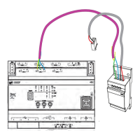
4. Disconnect the wire going to the outward part of the link (away from the Tracer
®
SC+). Connect the
alligator clips from the USB Comm4 adapter to the plus (+) and minus (-) terminals on the device and
run a SerialSpy capture.
If all devices are communicating and passing the token properly with no errors or diagnostics shown,
the problem exists on the outward side (away from the Tracer
®
SC+) of the broken link. If you see
errors and diagnostics, go to Step 8.
5. Perform a voltage check. Voltage should be between 0.3 V and 0.5 V. See Table 8, p. 41 for more
information.
6. Reconnect the link and move half-way farther out on the link and break the link there.
7. Disconnect the wire going to the outward part of the link (away from the Tracer
®
SC+). Connect the
alligator clips from the USB Comm4 adapter to the plus (+) and minus (-) terminals on the device and
run a SerialSpy capture.
If all devices are discovered, the problem exists on the outward side (away from the Tracer
®
SC+) of
the broken link.
8. Repeat Step 6 and Step 7 until the trouble is isolated.