41 BAS-SVX51L-EN
Troubleshooting Options
9. If you see errors and diagnostics, it is likely that there is an issue with the BACnet
®
link on the inward
side of the broken link.
10. Reconnect the link and move to the device that is half-way back toward the Tracer
®
SC+.
11. Disconnect the wire leading to the outward part of the link (away from the Tracer
®
SC+). Connect the
alligator clips from the USB Comm4 adapter to the plus (+) and minus (-) terminals on the device and
run a SerialSpy capture.
12. Repeat Step 4 and Step 5 until the problem is isolated.
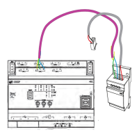
Network Voltage Measurement
The general procedure is to measure the dc voltage across the plus (+) and minus (-) communication
terminals at any device on the network. With terminators, the normal operating range that provides
adequate communication is 0.3V to 0.5V. Less than 0.2V is inadequate.
Note: You can obtain this voltage measurement with all devices on the link powered up and running.
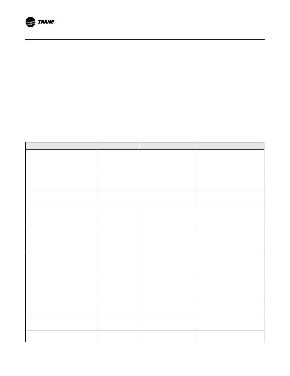
Table 8. Characteristics associated with specific problems on the BACnet
®
MS/TP link
Condition Vdc LEDs Serial Spy
Normal
Two powered Trane BACnet
®
terminators
Normal
(a)
Min = 0.33
Max = 0.60
Avg = 0.45
(refer to Note
(b)
)
Normal
Tx = quick flash
Rx = almost solid on
Normal
Clean token pass
No (or few) blue diagnostics or errors
(c)
One powered Trane BACnet
®
terminator
Min = 0.35
Max = 0.60
Avg = 0.45
(refer to Note
(b)
)
Normal
Tx = quick flash
Rx = almost solid on
Normal
Clean token pass
No (or few) blue diagnostics or errors
(c)
Two unpowered Trane BACnet
®
terminator
Min = 0.003
Max = 0.45
Avg = 0.21
(refer to Note
(b)
)
Normal
Tx = quick flash
Rx = almost solid on
Normal
Clean token pass
No (or few) blue diagnostics or errors
(c)
No Trane BACnet
®
terminators
Min = 1.1
Max = 2.2
Avg = 1.5
Normal
Tx = quick flash
Rx = almost solid on
Normal
Clean token pass
No (or few) blue diagnostics or errors
(c)
Cut the minus (-) comm wire
Normal
Min = 0.33
Max = 0.60
Avg = 0.45
(refer to Note
(b)
)
Normal
Tx = quick flash
Rx = almost solid on
Normal
Clean token pass
No (or few) blue diagnostics or errors
(c)
However, all units past the wire break stop
communicating — looks like two separate
links, each intact
Cut the plus (+) comm wire
Normal
Min = 0.33
Max = 0.60
Avg = 0.45
(refer to Note
(b)
)
Normal
Tx = quick flash
Rx = almost solid on
Normal
Clean token pass
No (or few) blue diagnostics or errors
(c)
However, all units past the wire break stop
communicating — looks like two separate
links, each intact
Minus (-) comm wire grounded
Min = 0.54
Max = 0.64
Avg = 0.58
(voltage range is very flat)
For units on the same transformer
Tx = quick flash
Rx = almost solid on
Other units are unaffected
All units sharing a transformer with grounded
units are comm down. The rest of the link is
normal.
Plus (+) wire grounded
Min = –0.50
Max = 0.16
Avg = 0.20
(voltage goes negative)
Normal
Tx = quick flash
Rx = almost solid on
Normal
Clean token pass
No (or few) blue diagnostics or errors
(c)
Comm polarity reversed
0.60 V
(very steady, no
fluctuation)
Tx = off
Rx = Weak flashing
Junk during idle — framing errors
Dead Short across the comm link 0 V
Tx = weak solid on
Rx = off or very weak
Junk during idle — framing errors
Bad header, fast scrolling