BAS-SVX51L-EN 11
Best Practices
Network Wiring Details
BACnet
®
wiring must use a daisy-chain configuration.
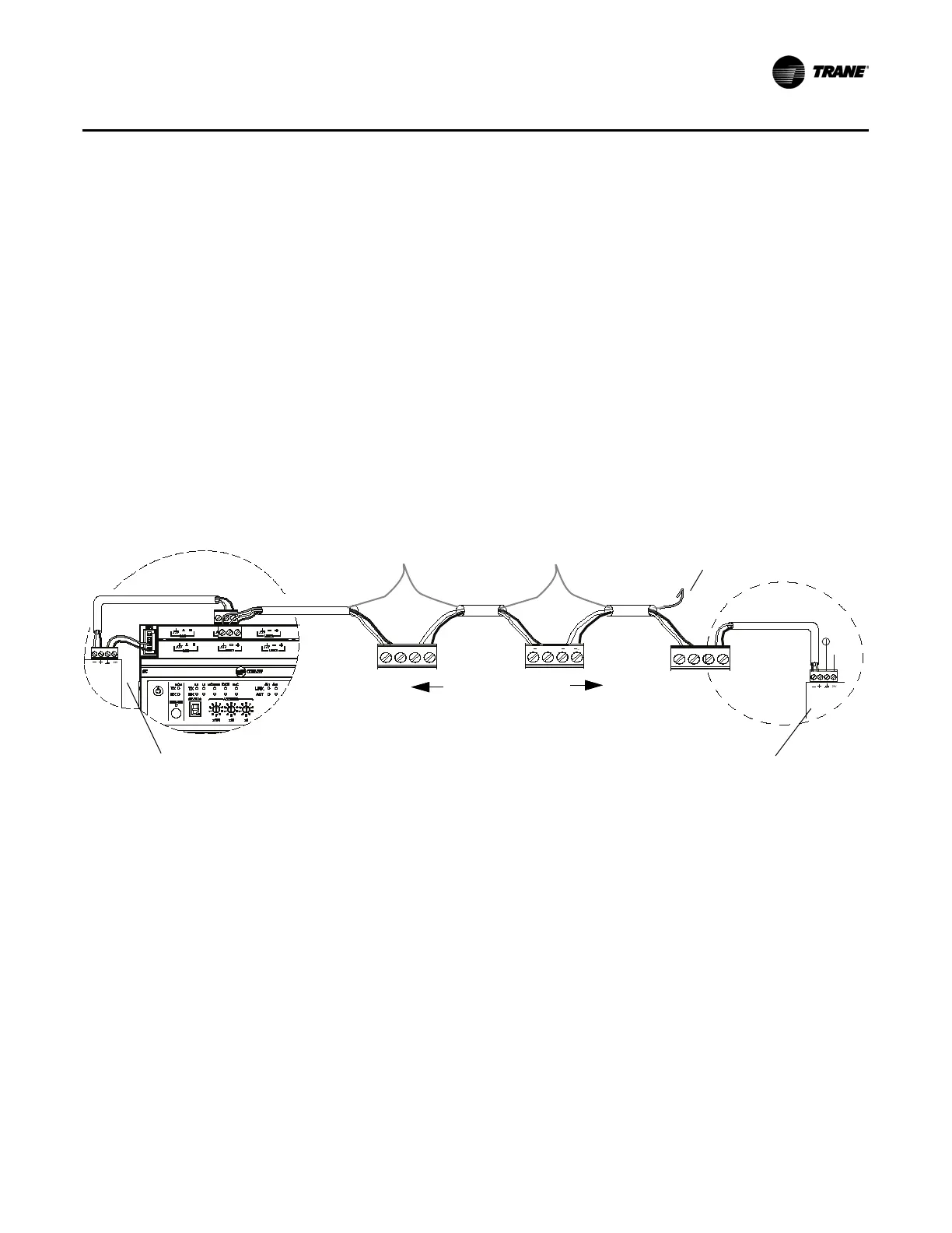
Follow these steps to connect communication wiring as shown in Figure 6.
1. Review the wiring diagram and determine which BACnet
®
MS/TP link is being wired.
Note: It is not necessary to place the Tracer
®
SC+ at the end of the of the communication link.
However, a Tracer
®
BACnet
®
Terminator must be wired at each end of the link.
2. Attach the communication wire between two adjacent devices on the link and verify that polarity of the
wires is maintained.
3. At each unit controller, join the shield wires together and insulate the connection with electrical tape
to prevent accidental shorting of the wire.
4. Repeat steps 2 and 3 for each unit controller on the link.
Note: For more information about the specific unit controller you are wiring, see the installation guide for
the specific controller.
Important: Tracer
®
unit controllers are not grounded on the DIN rail. It is necessary to ground each
controller to a good earth ground.
Figure 6. Daisy-chain configuration for BACnet
®
wiring
Note: The Tracer
®
UC800 cannot power a BACnet
®
terminator.
Observe the maximum link length recommendation
The maximum length of a 18 AWG network wire is 4,000 feet. The maximum lenght of a 22 AWG network
wire is 2,000 feet. Wire runs longer than recommended may experience communication issues.
Note: There is no support for repeaters on BACnet
®
MS/TP links.
Use a Tracer
®
BACnet
®
terminator at each end of the link.
Because the amount of communication signal degradation increases as the length of communication wire
increases toward the maximum of 4,000 ft. (1,219 m), Trane requires that a Tracer
®
BACnet
®
Terminator
(TBT) module (PN: X13651524-01) be connected at each end point of the network. For correct termination
placement, follow these guidelines:
• All BACnet
®
MS/TP links must be properly terminated. Use a Tracer
®
BACnet
®
terminator at each end
of the link.
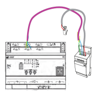
• Connect the communication wire shield to the ground terminal of the link termination block at the Tracer
®
SC+ as shown in
Figure 7
. The Tracer
®
SC+ provides the ground for the BACnet
®
MS/TP link. This is the
only place on the link that the shield wire should be grounded.
+
+
24 VAC
Tracer
®
BACnet
®
terminator
Tracer
®
BACnet
®
terminator
Twist wire and
tape shields
Tape back
Unit Controllers
(Power Side)
(Each UC should be
grounded to a good earth
ground.)