Do you have a question about the Trane BAYSENS019C and is the answer not in the manual?
Details of WARNING, CAUTION, and CAUTION alerts for safe operation.
Explanation of how model numbers identify specific unit types and components.
Describes the manual's purpose and content for installers and technicians.
Steps for inspecting the received kit for damage and missing components.
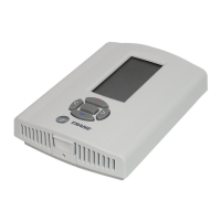
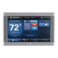
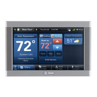
Overview of the BAYSENS019C programmable sensor features and compatibility.
Instructions for selecting a location and mounting the sensor and its sub base.
Details on identifying terminals for power, sensors, communication, and inputs.
Connecting the 24 VAC power supply from the Unit Control to the ZSM.
Connecting an optional remote thermistor sensor to the ZSM.
Wiring for serial data communication between the UCM and the ZSM.
Connecting UCM status signals (HEAT, COOL, SYSTEM, SERVICE) to the ZSM.
Information on the auxiliary relay and connecting wires to the sub base terminals.
Connecting wires to the appropriate terminals at the unit control panel and sub base.
Steps for initial power-up, verifying wiring, and setting day and time.
Accessing and configuring programmable options via the Option Menu.
Guides for programming the sensor's schedule, including daily periods and set points.
Method for quickly programming multiple days using a single day's settings.
Changing temperature set points, Mode, or Zone status for a limited time.
Steps to enter and set parameters for the temporary override function.
Procedures for exiting the temporary override mode and returning to normal operation.
Understanding the display during an active override period.
Explains the meaning of various icons indicating system status or faults.
Instructions on how to replace the battery backup for the zone sensor.
| Model | BAYSENS019C |
|---|---|
| Type | Temperature Sensor |
| Power Supply | 24V AC |
| Series | BAY |
| Color | White |
| Connectivity | Wired |
| Relative Humidity Range | 5% to 95% non-condensing |
| Mounting | Wall-mounted |
| Sensor Type | Temperature |
| Product Type | Sensor |
| Programmability | No |
| Power Source | Wired |
| Input Types Supported | Temperature |
| Operating Temperature | 32°F to 122°F |
| Agency Listings | UL, cUL |
| Compatibility | Trane communicating systems |
| Inputs | Remote sensor |