CGAD-SVN02C-EN8
Dispatch and Handling
1. The CGAD Cooling units leave the plant
ready to be installed, tested as needed,
and with the correct level of oil and
refrigerant for operation.
2. When the unit arrives, compare all the
data on the plate with the information on
the order and invoice.
3. In order to receive the unit, run a visual
check on all the components, tubing, and
connections in order to make sure that
there are no dents or leaks caused by
handling during transportation. If there are
any problems, notify the transportation
company and Trane do Brasil immediately.
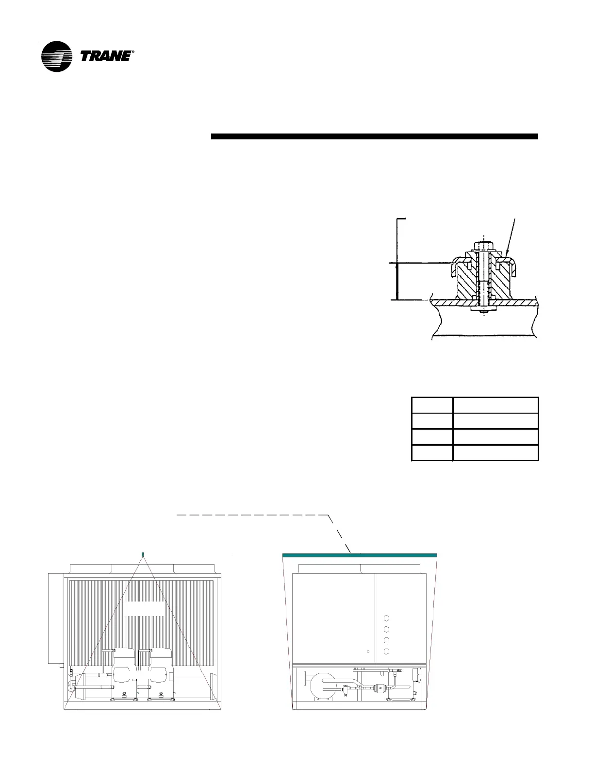
4. The CGAD Cooling units come with
hoisting supports along both sides of the
unit's profile made up of four holes. Put the
hoisting cables through the holes and set
extension bars between the cables on the
top part of the unit (fig. 2). This way, when
the equipment is hoisted correctly, it will
remain in its center of gravity. The loading
weights are shown on table 2.
5. The chains, ropes, or steel cables
should not touch the equipment.
6. During transportation, do not tip or lean
the equipment more than 15° from the
vertical position.
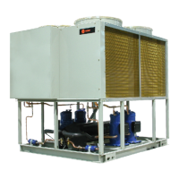
7. The compressors are fixed to their
support tracks with the bolts from the
rubber pads themselves and they leave
the plant tight for protection against
movements that could cause the tubing to
break. The operation and loading position
in this type of pad is the same.
Support and Fastening Base
1. In order to fix the CGAD unit in place,
there must be a support base that is
perfectly level and smooth. Also make sure
that the location for the unit is sufficiently
resistant to withstand its weight and
absorb the vibrations of the unit.
2. We recommend using skids or vibration
arrestors under the unit's support feet. The
rubber pad-type vibration arrestors should
be installed between the unit's feet and the
base surface. If the equipment is installed
on top of cement slab or roof, spring-type
vibration arrestors should be purchased.
We do not recommend the use of shock
absorbers of springs vibration.
3. Mark the support points on the flooring
and be careful when moving the unit
horizontally and vertically.
Transportation
and Movement
U-Beam 3” x 1 1/2” x 0.25” x 100”
Fig. 02 - Fastening the compressor
Fig. 03 - Transportation and movement instruction
CONDENSER
COIL
COMPRESSORS
ELECTRICAL
PANEL
PRESSURE
GAUGES
Model Dimension "A"
020 57''
025-030 71''
040-090 78,8'
Working
height
Base
Compressor