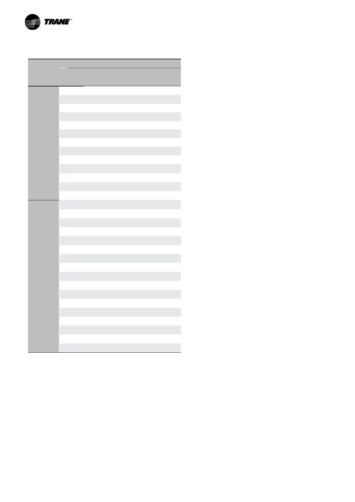
Page 19
7.1.1
Calculation of total minimum water content, total optimal water content and flow rates
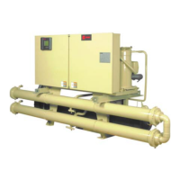
CGWF SE
Plant side chilled water heat exchanger
Vopt Vmin K Q min Q max
[m3] [m3] [m3/h] [m3/h]
One refrigerant circuit sizes
050 0,45 0,26 365,3 5,6 14,9
060 0,51 0,29 358,0 6,4 16,9
065 0,57 0,32 352,4 7,1 18,9
080 0,69 0,39 182,4 8,6 22,9
090 0,78 0,45 178,5 9,8 26,1
110 0,93 0,53 75,6 11,6 31,0
125 1,07 0,61 73,8 13,4 35,6
135 1,17 0,67 72,7 14,7 39,2
150 1,28 0,73 71,7 16,0 42,6
170 1,45 0,83 38,5 18,2 48,5
190 1,64 0,94 27,1 20,5 54,6
215 1,85 1,06 26,6 23,1 61,6
235 2,04 1,16 26,2 25,5 67,9
Two refrigerant circuits sizes
115 0,95 0,54 119,4 11,9 31,6
120 1,01 0,58 118,5 12,7 33,7
130 1,14 0,65 117,0 14,2 37,9
155 1,33 0,76 56,4 16,7 44,4
185 1,57 0,90 55,3 19,6 52,3
210 1,81 1,03 54,5 22,6 60,2
245 2,11 1,21 30,8 26,4 70,5
270 2,33 1,33 30,5 29,1 77,5
290 2,52 1,44 30,3 31,4 83,8
340 2,92 1,67 11,6 36,5 97,4
375 3,21 1,83 11,4 40,1 106,9
420 3,63 2,07 11,2 45,4 121,0
475 4,10 2,34 6,3 51,3 136,7
555 4,78 2,73 6,1 59,7 159,2
610 5,27 3,01 3,6 65,8 175,5
660 5,69 3,25 3,6 71,2 189,8
700 6,00 3,43 3,6 75,0 200,0
LEGEND:
Vmin
: minimum water content of the plant
Vopt
: optimal water content of the plant
Q min
: minimum water flow to the heat exchanger
Q max
: maximum water flow to the heat exchanger
ΔTmax chiller = 10 °C
ΔTmin chiller = 3 °C
dpw = K·Q² / 1000 Q = 0,86 P/ΔT