Page 11
4 INSTALLATION
4.1
MOVING AND POSITIONING THE UNIT
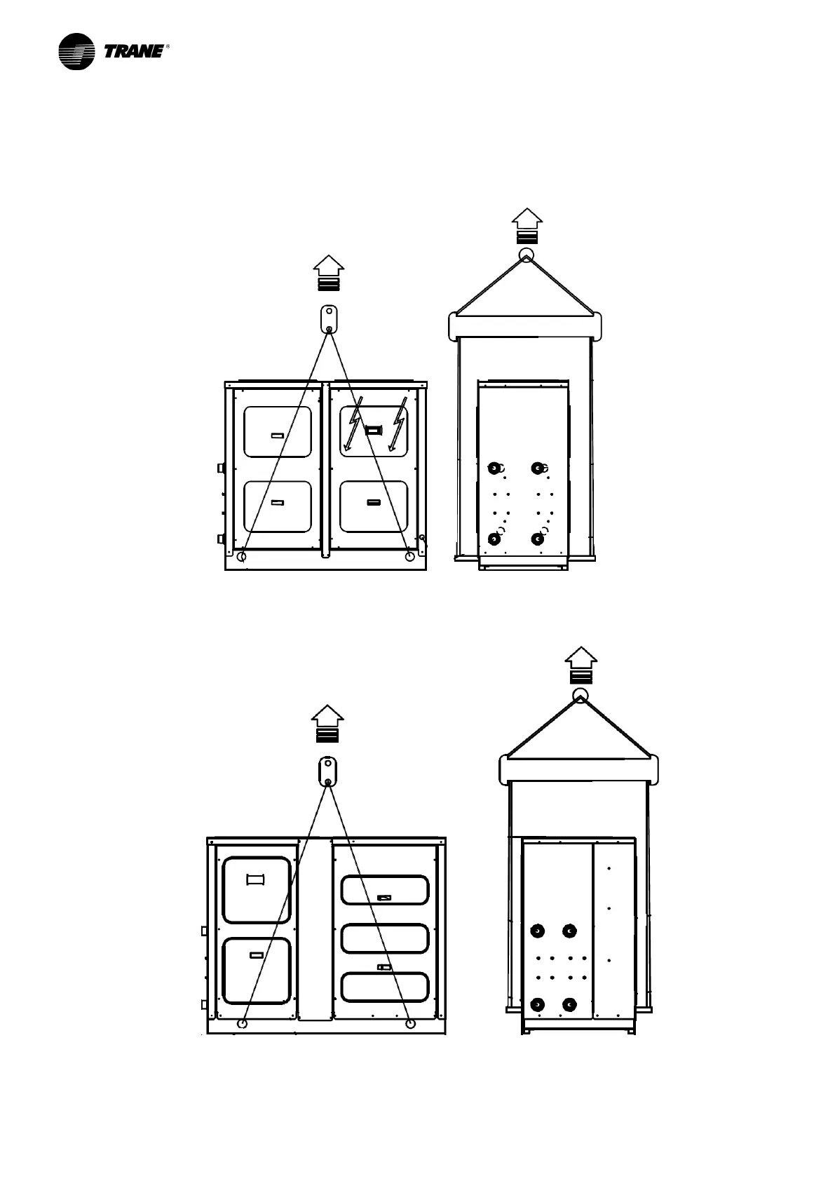
The units have been designed to be lifted from above by means of eyebolts and holes in the base frame .
Use retractor bars to keep the lifting wires or chains away from the unit.
Figure 2 - Correct lifting procedure for platform 1 units
(CGWF SE sizes from 050 to 090, CGWF HE sizes from 055 to 095
and CXWF sizes from 060 to 110)
Figure 3 - Correct lifting procedure for platform 2 units
(CGWF SE sizes from 110
to 235
, CGWF HE sizes from 110
to 155 and CXWF sizes from 125 to 175)