CVHE-SVN02D-EN
10
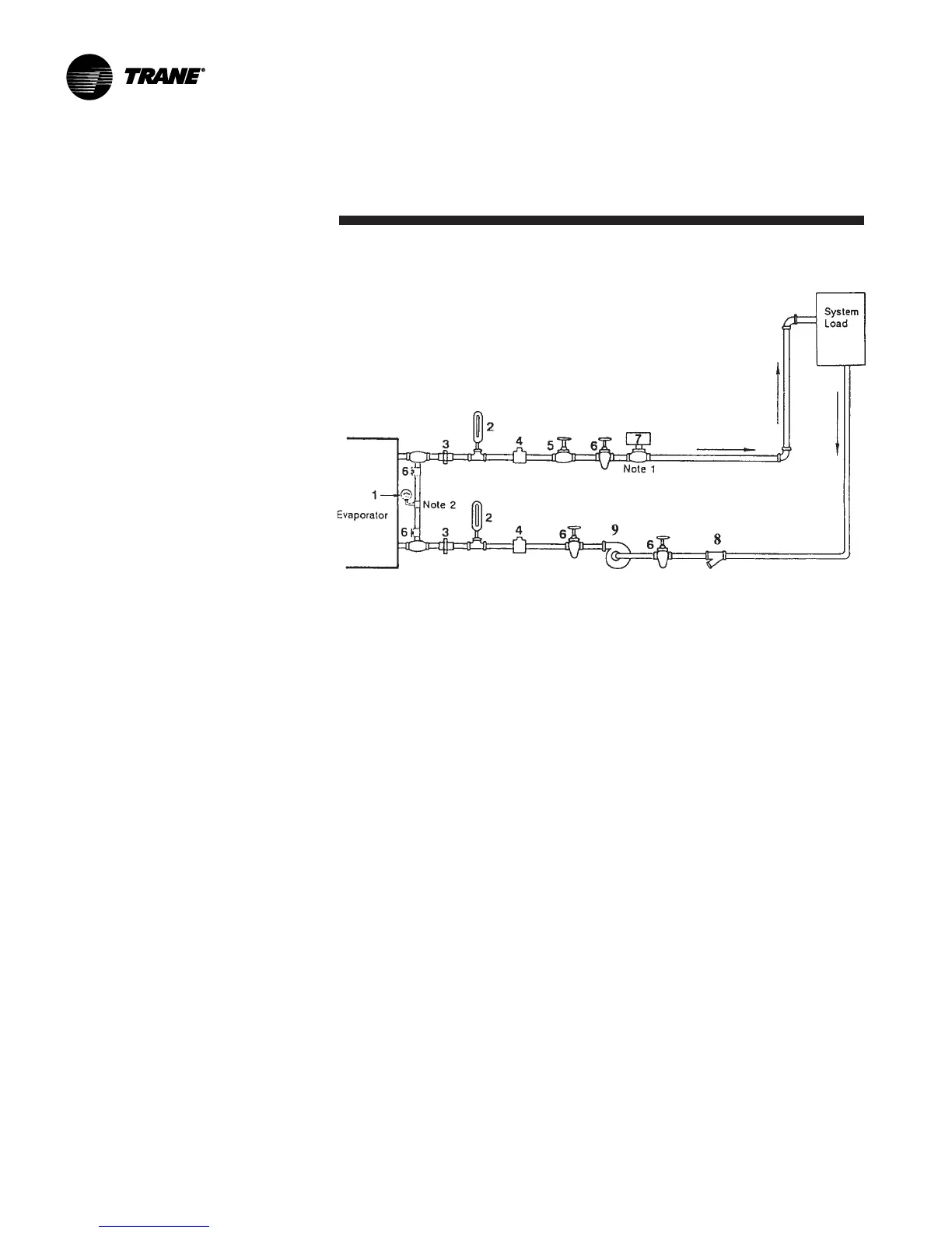
Water Piping
Notes:
1. Flow switch 5S1 (Item 7 in Legend of Components) may be installed in either the entering or leaving leg of
the chilled water circuit.
2. It is recommended to pipe the (Item 1) gauge between entering and leaving pipes. A shutoff valve on each
side of the gauge allows the operator to read either entering or leaving water pressure.
Legend of Field-Supplied and Installed Components
1. Pressure Gauge
2. Thermometer(s) (If field supplied)
3. Union(s) or Flanged Connection(s)
4.1/2" [13 mm] NPT Couplings
5. Balancing Valve
6. Gate (Isolation) Valve(s) or Ball Valve(s)
7. Chilled Water Flow Switch (5S1)
8. Strainer
9. Evaporator Water Pump
Figure 3. Typical evaporator water piping circuit
 Loading...


