15
CVHE-SVN02D-EN
Water Piping
Table 4. Installation data for 150 PSIG flange adapters (Style 741)
Nominal Assembly Number of Bolt Pattern
Pipe Size Bolt Size* Assembly Diameter Weight
Inch mm Inch mm Bolts Required Inch mm Pounds kg
4 114.3 5/8 x 3 16 x 76 8 7.5 191 7.7 3.5
5 141.3 3/4 x 3-1 /2 19 x 89 8 8.5 216 9.3 4.2
6 168.3 3/4 x 3-1/2 19 x 89 8 9.5 241 10.3 4.7
8 219.1 3/4 x 3-1 /2 19 x 89 8 11.75 298 16.6 7.5
10 273.0 7/8 x 1/4 22 x 6 12 14.25 362 24.2 11.0
12 323.9 7/8 x 1 /4 22 x 6 12 17 432 46.8 21.2
14 355.6 1 x 4-1 /2 25 x 114 12 18.75 476 75 34.0
16 406.4 1 x 4-1 /2 25 x 114 16 21.25 540 90 40.8
Table 5. Installation data for 350 PSIG flange adapters (Style 743)
Nominal Assembly Number of Bolt Pattern
Pipe Size Bolt Size* Assembly Diameter Weight
Inch mm Inch mm Bolts Required Inch mm Pounds kg
4 114.3 3/4 x 3-3/4 19 x 95 8 7.88 200 15.3 6.9
5 141.3 3/4 x 4 19 x 102 8 9.25 235 17.7 8.0
6 168.3 3/4 x 4-1/2 19 x 114 12 10.63 270 23.4 10.6
8 219.1 3/4 x 4-3/4 19 x 121 12 13 330 34.3 15.6
10 273.0 1 x 5-1 /4 25 x 133 16 15.25 387 48.3 21.9
12 323.9 1-1 /8 x 5-3/4 29 x 146 16 17.75 451 70.5 32.0
*Or equivalent supplied by others.
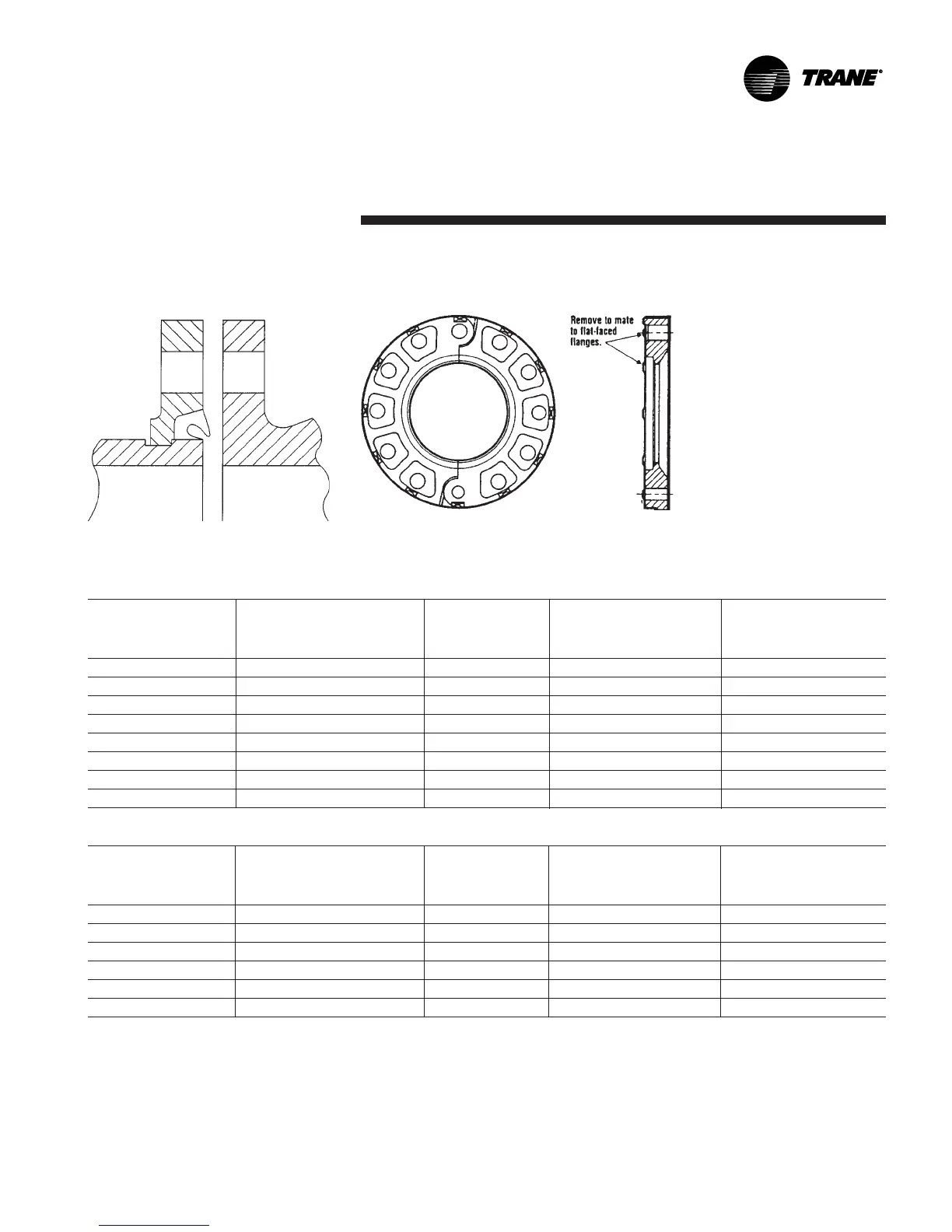
Figure 8. Typical victaulic flange
gasket configuration
Figure 9. Modifying 300 PSIG flange adaptors for flat-faced flange application
 Loading...


