18
PKGP-SVX19A-EN
Installation - Mechanical
a temperature sensor on the main supply pipe of the water system so that the supply water temperature sensor of the
system can be installed.
24.
Hydraulic Test:
After the installation and connection of the water system pipeline, hydraulic test should be carried out.
The accuracy of the pressure gauge should be higher than 0.01MPa, and the test pressure is 1.5 times the highest working
pressure. If the hydraulic test is done together with the heat exchanger of the unit, the maximum test pressure must not
exceed 1.0MPa (except for specially designed products) to avoid damage to the components on the chilled-water side of
the unit. The exhaust valve must be opened when lling water, and then closed after the air fully exhausted and water fully
lled. If a leakage occurs in the hydraulic test, it must be repaired immediately, and then do the hydraulic test again until no
leakage happens.
25.
Cleaning:
The water system must be cleaned before the unit is started or debugged. When cleaning, the water system
must be separated from the unit, and the water system must be circulated and cleaned separately to ensure that the water
system is free of impurities. Then the water system can be connected to the unit for start-up and debugging. The water lter
needs to be cleaned regularly depending on the cleanliness of the water system during the operation of the unit to avoid
the performance degrade of the unit caused by water ow being too small, or even the stop of the unit caused by water ow
alarm or antifreeze protection alarm of the unit.
26.
Control wiring of external water pump:
The external water pump needs to be equipped with a starter, for which the
control wiring must be connected to the output of the water pump of the host unit. The water pump control should be linked
with host unit to ensure the automatic protection function of the unit.
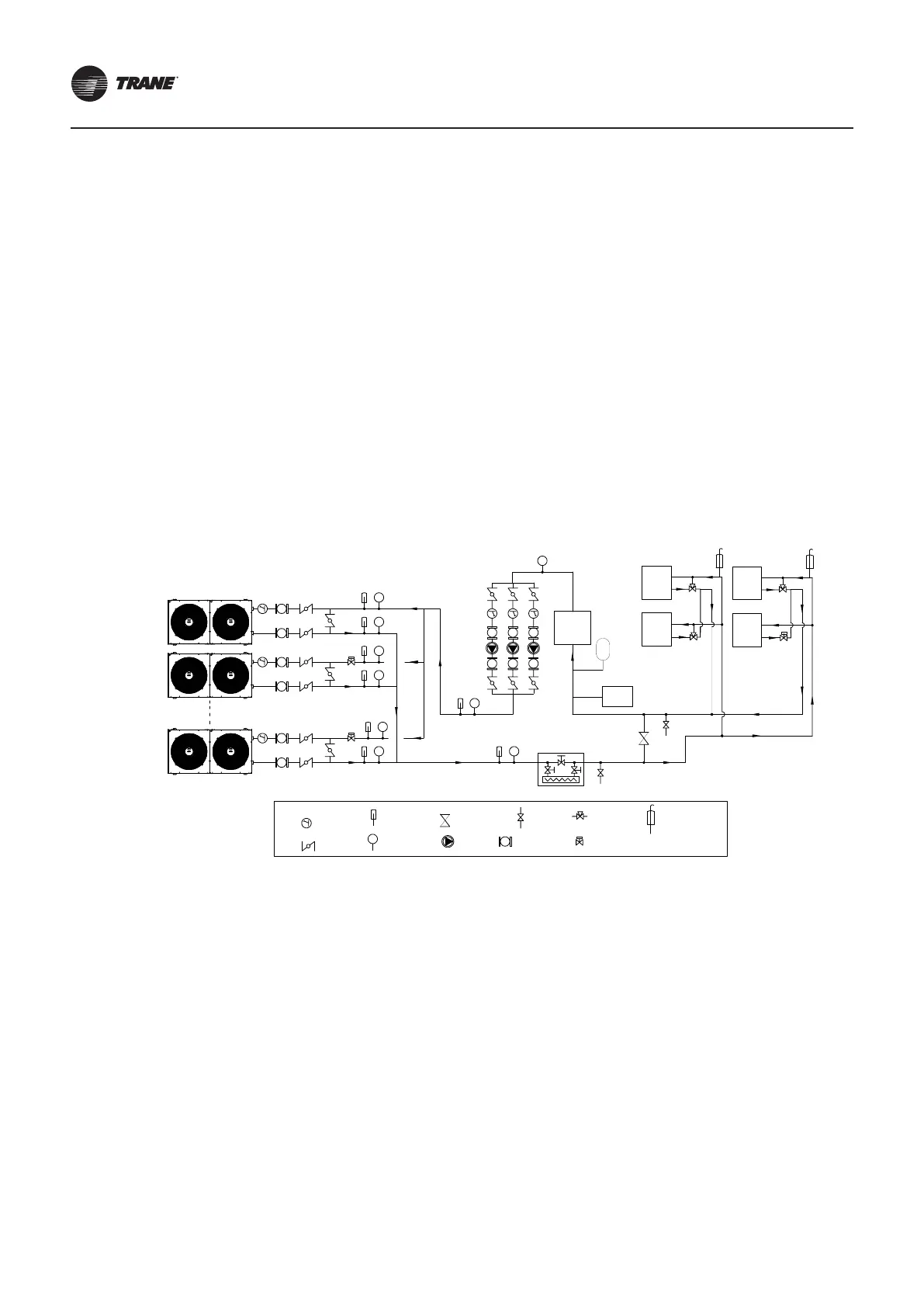
27.
Installation schematic diagram of closed-type constant-ow water system (air conditioning application)
Auxiliary Electric Heater
(Optional)
Terminal
Closed Type
Water Tank
Soften Water
Device
Constant Pressure
Water Make-up
Filter
Shut-off
Valve
Water Pressure.
Sensor
Temp. Sensor
D.P
Bypass
Valve
Pump
Anti-vibration
Flexible Connection
Drain
Valve
Three-way
Valve
Two-way
Valve
Auto Exhaust
Valve
Water pump is configured according to actual situation.
Note⑤
Note②
Host Unit
Slave Unit 1
Terminal
Terminal
Terminal
Technical Notes:
When multiple units are connected, reversed return water system should be applied to ensure the uniformity of the water ow
of the unit.
1). When multiple units are connected, reversed return water system should be applied to ensure the uniformity of the water
ow of the unit
2). when cleaning the water system, it is necessary to shut o all the shut-o valves at entering and leaving the unit, and open
the bypass valve to avoid impurities in the water system from entering the unit and aecting the life of the unit.
3). The default control of the unit is entering water temperature control, in-build ow switch exists in most models.
4). For those unit with a three-way valve or two-way valve installed on terminals, the water ow through the operating unit
should meet the requirement of the unit at any running time.
5). For variable water ow system, two-way valve should be installed at entering port the unit and connected to the PCB
board of the corresponding unit, refer to the electrical diagram interface of the unit. The two-way valve is not requested for
constant water ow system.