27PKGP-SVX19A-EN
Pre-Start
Check List Before Start
1. Check the connection of all wiring, all electrical contacts should be clean and rmly locked.
2. Check whether power supply voltage is normal.
3. Fill the chilled water system, keep the exhaust valve of the system open when lling, and close it when water lling
completed.
4. Ensure that the water owrate meets the water owrate requirements of the unit, and there is no water ow switch alarm.
5. Turn on the main power supply, start the unit by pressing the switch button on the control panel. The water pump should
start, the water circulates in the chilled water system, and check whether there is leakage at any piping connections.
6. Adjust the water ow in the chilled water circuit and check the external water pressure of the unit (standard model) or
evaporator pressure drop (model without built-in pump) meet requirement.
7. Stop the pump and turn o all the power.
Voltage Range
The power supply of the unit must comply with the operating power supply indicated on the nameplate of the unit, and the
imbalance between the power supply voltage and the nameplate voltage and the imbalance between each phase must be
within the following range. The voltage between the phases should be measured, and the reading must be within the allowable
tolerance (±10%). If the voltage imbalance between any two phases is not within this tolerance, please contact power company
to improve before starting the unit. Improper voltage can cause abnormal control functions and shorten the life of various
electrical components and compressor motors.
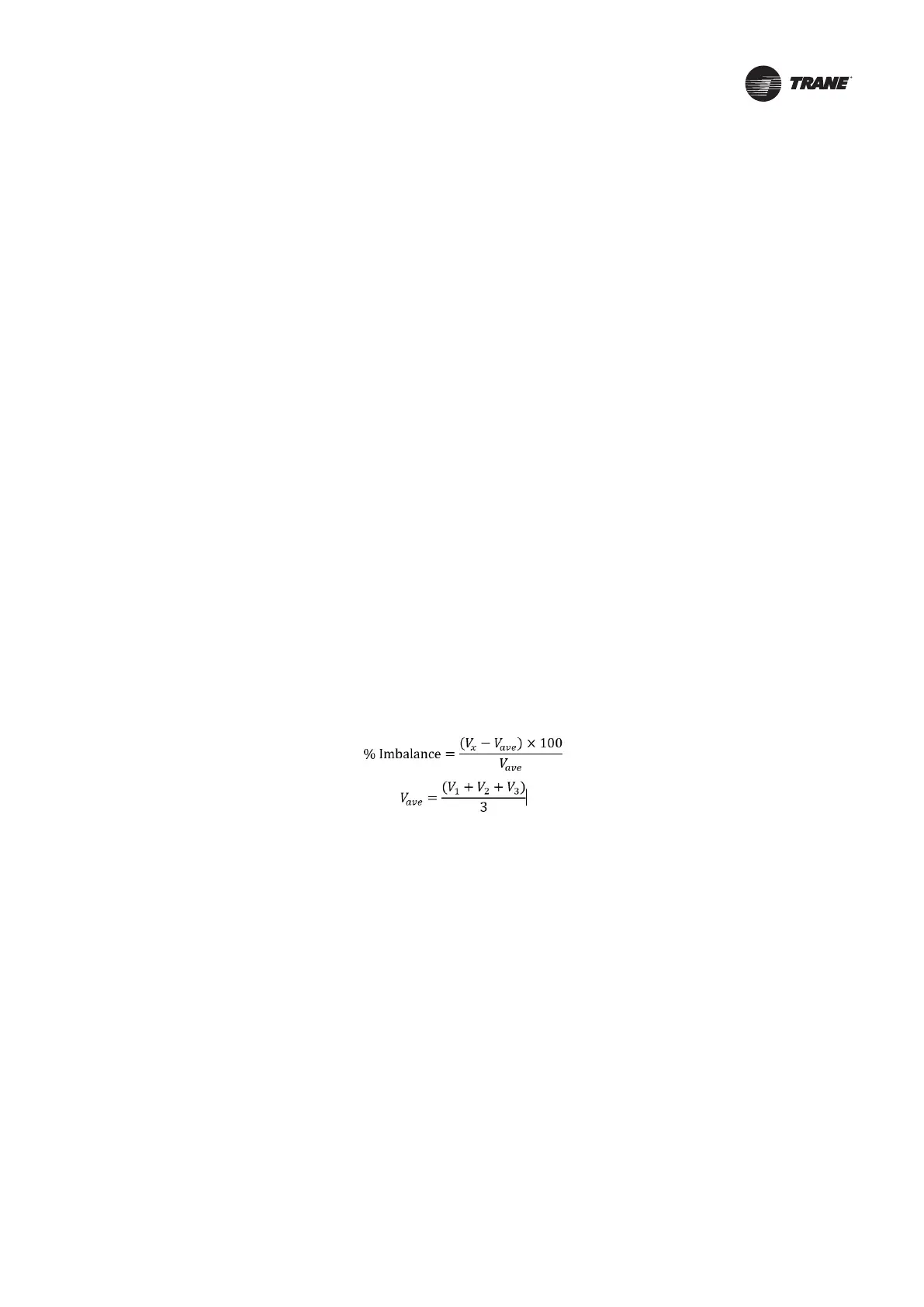
Voltage Imbalance
Too large voltage imbalance between the phases in the three-phase power system will cause motor to overheat or failure. The
maximum allowable unbalanced voltage is 2%, and voltage imbalance is dened as follows:
V
x
= phase with greatest dierence from V
ave
(without regard to the sign)
Unit Settings
Please set the function and operating parameters of the unit according to the installation operation manual before starting or
commissioning the unit. The settings include connection jumpers, dene of DIP switches and system bits. Incorrect settings
can lead to undesired function or even non-operation of the unit.
Unit Dial Switch Setting/Host and Slave Unit Dial Switch Setting
Unit PCB arrangement is as follows: