24
PKGP-SVX19A-EN
Installation - Electrical
13. When using the remote switch, connect the remote switch between terminals 10 and 11, press the power on button of the
centralized control screen, and set the power-o memory function to be eective, and then control the unit by on/o signal.
14. When not using the remote switch, please short-circuit and turn on/o the unit by the centralized control screen.
15. The reserved remote mode switching signal should be connected between terminals 12 and 13.
16. The reserved pump overload signal should be connected between terminals 16 and 17.
17. The reserved water circuit electric heating overload signal should be connected between terminals 18 and 19.
18. External water ow switch for units not equipped with water ow switch could be connected between terminals 14 and 15.
19. For specic wiring, refer to the unit circuit diagram.
Wiring Sizing
The minimum current, fuse specications, and motor electrical specications are shown in the following table:
Model Power Supply
Maximum Operation
Current MOC(A)
Recommended minimum
fuse size REC(A)
Recommended minimum
breaker In(A)
Minimum size of copper core
power wiring(AWG)
CXAU0655BVS 380/50/3 65 91 82 4 AWG
CXAU1305BVS 380/50/3 115 161 144 1 AWG
CXAU0656BVS 380/60/3 65 91 82 4 AWG
CXAU1306BVS 380/60/3 15 161 144 1 AWG
CXAU0657BVS 460/60/3 55 77 69 6 AWG
CXAU1307BVS 460/60/3 96 135 120 2 AWG
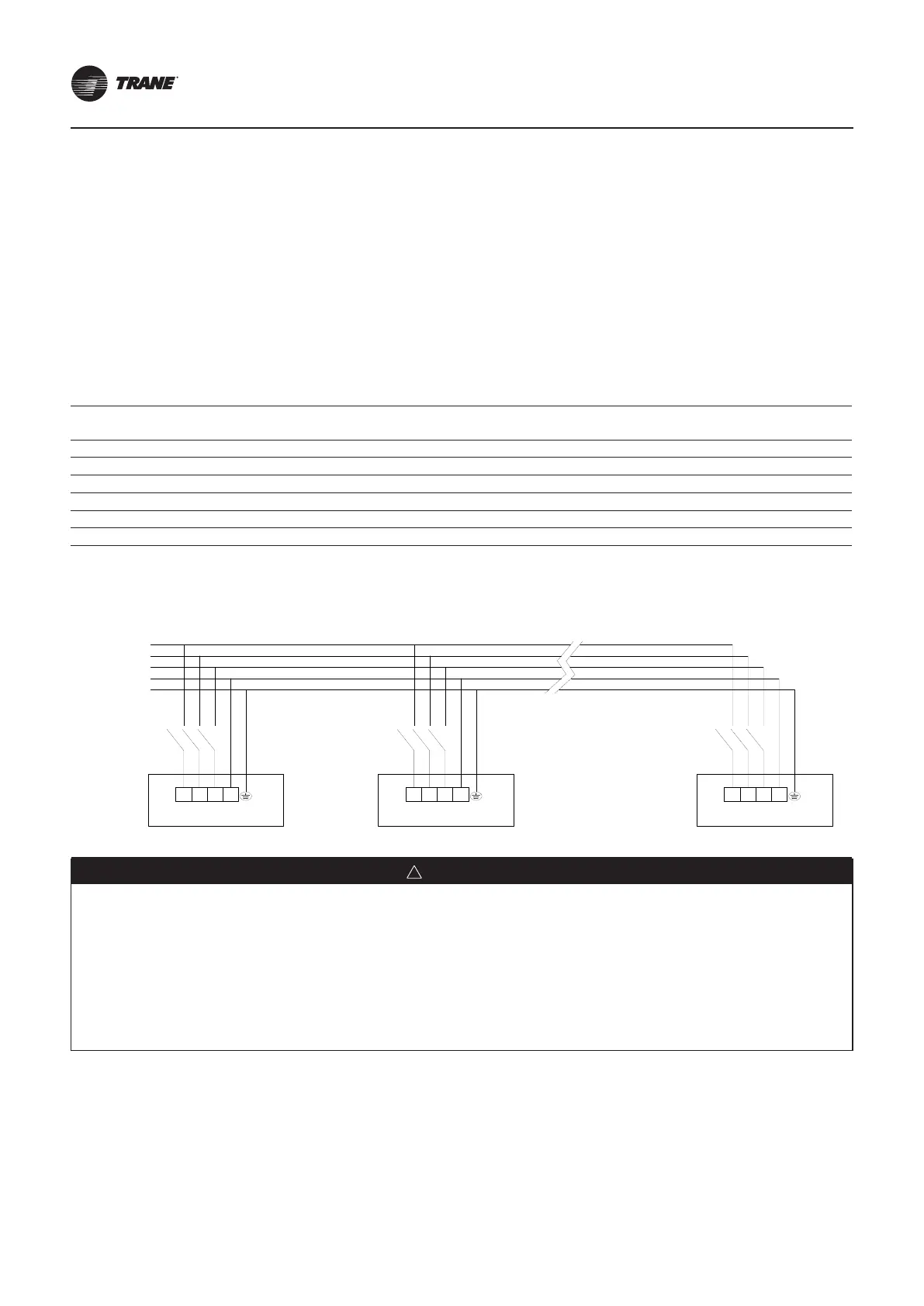
Unit Power Connection Diagram
L1
L2
L3
N
PE
16#Unit2#Unit
U V W N PE
Circuit Breaker
1#Unit
Circuit Breaker Circuit Breaker
U V W N PE U V W N PE
WARNING
●
The installation site should provide power supply that meets the requirements of the unit and a suitable circuit
breaker, and the power supply voltage uctuates within ±10% of the rated voltage.
●
Before the completion of electrical wiring, please do not energize to avoid casualties.
●
The unit with 380V/460V scroll compressor is equipped with controller protection of power inverter and phase
loss. The protection function should be checked before starting the unit. Green light indicates normal; red light
indicates inversion; yellow light indicates phase loss. In the case of phase inverting or phase loss, the unit
will be automatically prohibited to start-up. The phase inverting or phase loss protection is only for the power
supply of the unit.
Field Wiring Instructions