Do you have a question about the Trane FC and is the answer not in the manual?
Provides overview of the manual, its history, and warnings/cautions.
Explains the meaning of WARNING and CAUTION messages used in the manual.
Lists and defines common acronyms and abbreviations used in the manual.
Lists related Trane publications for UniTrane fan-coil and Force Flo equipment.
General information about the UniTrane fan-coil and Force Flo units.
Provides physical dimensions and weight specifications for various unit sizes.
Details site preparation and considerations before unit installation.
Covers ductwork, piping, and other mechanical installation aspects.
Details electrical connections, wiring, and safety requirements.
Step-by-step instructions for installing the units.
Lists essential checks before initiating unit startup.
Detailed breakdown of each digit in the model number and its meaning.
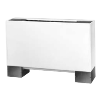
Illustrations and names of various available fan-coil unit models.
Diagrams showing different factory-installed piping package configurations.
Dimensions and mounting details for the Vertical Concealed Model A.
Diagrams showing coil connection locations for fan-coil units.
Diagrams showing coil connection locations for Force Flo units.
Diagrams and dimensions for fresh air openings.
Details on wall box dimensions and installation requirements.
Dimensions and installation details for projection panels.
Procedures for inspecting units upon delivery and handling them safely.
Key considerations for proper unit placement and installation.
Details on accessing units for service and maintenance.
Checklist to ensure all installation procedures are complete.
Step-by-step instructions for connecting field piping to the unit coil.
Procedures for installing and connecting the condensate drain system.
Installation and function of the automatic electric heat lockout switch.
Procedure for venting the hydronic coil to ensure proper water flow.
Procedure for setting the manual circuit setter valve for proper water flow.
Guidance on sizing field supply wiring and circuit protection.
Rules and recommendations regarding electrical grounding.
Instructions for wiring wall-mounted controls to the unit.
Formulas and guidelines for calculating MCA and MFS for electric heat units.
General procedures for installing vertical and horizontal units.
Detailed instructions for installing wall-mounted controls.
Details on communication wiring specifications and installation for Tracer units.
Best practices for installing communication wiring to ensure reliability.
Checklist to verify completion of all installation procedures before unit startup.
Ensuring the unit is placed in an adequate location with proper clearances.
Ensuring the unit is installed level for proper operation.
Procedure for starting up Tracer ZN510 and ZN520 units.
Steps for operating Tracer ZN510/ZN520 controllers in standalone mode.
Overview of relay boards, fan mode switches, and Tracer controllers.
Description of the relay board's function and components.
Information on the manual fan mode switch and its operation.
Overview of Tracer ZN010 and ZN510 controllers for fan-coil units.
Describes fan mode switch and Tracer controller operation sequences.
Explains how the fan mode switch controls fan operation.
Details operation modes for Tracer ZN010/ZN510 controllers.
Explains the operation modes for the Tracer ZN520 controller.
Explains how the controller samples entering water temperature.
Details the functions of the controller's binary inputs.
Lists and describes the controller's binary outputs.
Details the analog inputs accepted by Tracer ZN010/ZN510 controllers.
Information on zone sensors and their inputs.
Details the operational sequences for the Tracer ZN520 controller.
Describes the unit's operation in occupied mode.
Describes the unit's operation in unoccupied mode.
Details how the Tracer ZN520 controller manages cooling operation.
Details how the Tracer ZN520 controller manages heating operation.
Explains how the controller performs dehumidification.
Explains fan operation based on mode settings and controller flexibility.
Describes how electric heat is controlled by the Tracer ZN520.
Instructions for adjusting the manual fresh air damper.
Explains economizer damper operation with Tracer ZN520.
Information on zone sensors and their inputs.
Functionality of the On/Cancel buttons on the zone sensor.
Use of the RJ-11 jack for communication with controllers.
Details on Tracer ZN520 controller communication via LonTalk.
Information on Tracer ZN520 controller diagnostics and their effects.
Table listing diagnostics, their status, and the impact on unit outputs.
Methods for resetting controller diagnostics.
Procedure for performing a manual output test to verify operation.
Tables listing probable causes for common operational issues.
Guidance on troubleshooting the Tracer ZN010, ZN510, and ZN520 controllers.
Step-by-step procedure for performing the manual output test.
General procedures for maintaining unit operation.
Instructions for changing or cleaning air filters.
Procedures for inspecting and cleaning drain pans.
Instructions for cleaning and maintaining coils.
Procedure for removing the fan board assembly for coil or motor repairs.
Recommended monthly and annual maintenance schedule.
Schematics of typical electrical wiring configurations for the units.
Wiring diagram for Tracer ZN010 with electric heat.
Wiring diagram for Tracer ZN510 with main and auxiliary valves.
Wiring diagram for ZN520 with 2-stage electric heat.
| Brand | Trane |
|---|---|
| Model | FC |
| Category | Air Conditioner |
| Language | English |