16
RT-SVX096A-EN
Weights
Table 1. Maximum unit and corner weights (lb) and center of gravity dimensions (in.)
Tons Unit Model No.
Weights (lb)
(a)
,
(b)
Corner Weights
(c)
Center of Gravity (in.)
Shipping
Net A B C D
Length
Width
7.5 GDK090A 1087 1025 247 246 265 267 44 33
8.5 GDK102A 1124 1063 254 246 275 287 43 35
10 GDK120A 1157 1096 289 242 257 317 38 33
12.5 GDK150A 1237 1175 306 257 278 344 38 34
7.5 EDK090A 979 917 221 220 237 238 44 33
8.5 EDK102A 1016 955 228 221 247 258 43 35
10 EDK120A 1047 985 260 217 231 284 38 33
12.5 EDK150A 1127 1065 277 233 252 311 38 34
(a)
Weights are approximate. Horizontal and downflow unit and corner weights may vary slightly.
(b)
Weights do not include additional factory or field installed options/accessories.
(c)
Corner weights are given for information only. 7.5 to 12.5 ton models must be supported continuously by a curb or equivalent frame support.
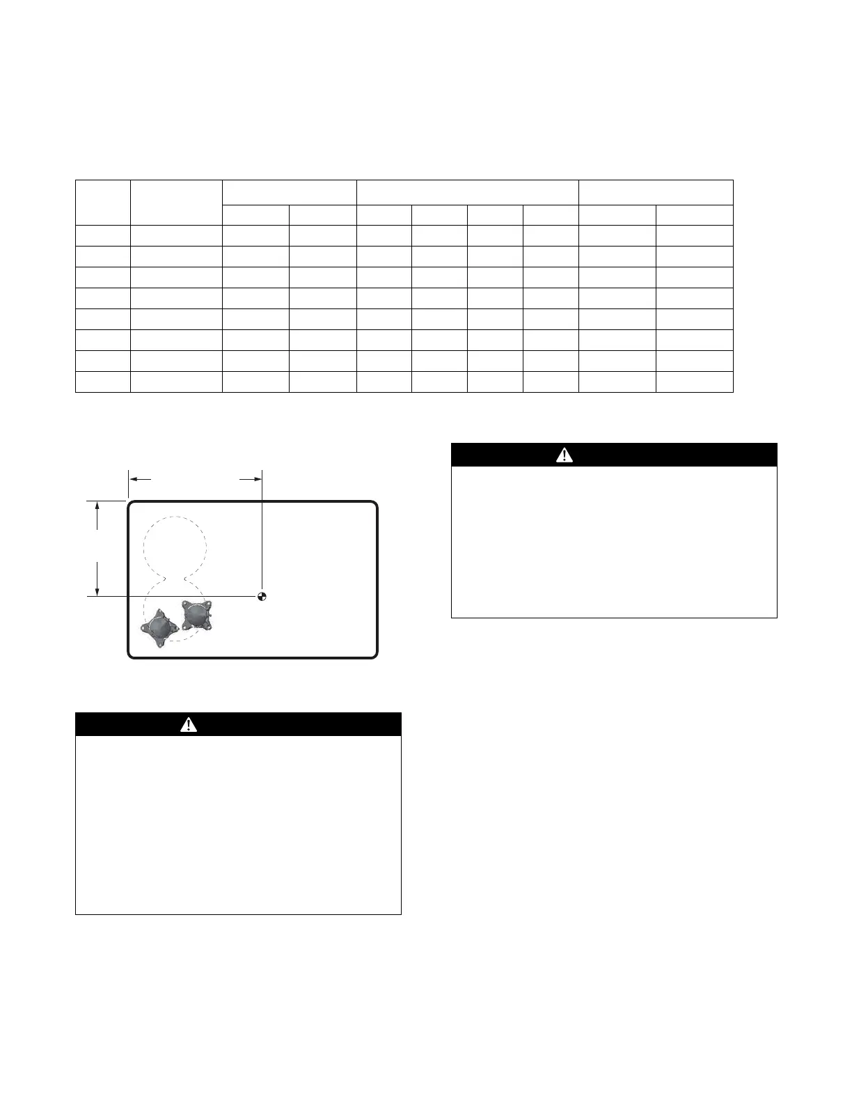
Figure 8. Center of gravity/corner weights
A
B
CD
CENTER OF GRAVITY
LENGTH
CENTER OF
GRAVITY
WIDTH
Rigging
WARNING
Heavy Object!
Failure to follow instructions below could result in
unit dropping which could result in death or serious
injury, and equipment or property-only damage.
Ensure that all the lifting equipment used is properly
rated for the weight of the unit being lifted. Each of the
cables (chains or slings), hooks, and shackles used to
lift the unit must be capable of supporting the entire
weight of the unit. Lifting cables (chains or slings)
may not be of the same length. Adjust as necessary
for even unit lift.
WARNING
Improper Unit Lift!
Failure to properly lift unit in a LEVEL position could
result in unit dropping and possibly crushing
operator/technician which could result in death or
serious injury, and equipment or property-only
damage.
Test lift unit approximately 24 inches (61 cm) to verify
proper center of gravity lift point. To avoid dropping of
unit, reposition lifting point if unit is not level.
Refer to Figure 9, p. 17 and for typical unit operating
weights rigging before proceeding.
1. Remove the shipping crate from around the unit. Do not
remove the crating from the top of the unit.
2. Rig the unit as shown in Figure 9, p. 17. Attach
adequate strength lifting slings to all four lifting brackets
in the unit base rail. Do not use cables, chains, or slings
except as shown.
3. Install a lifting bar, as shown in Figure 9, p. 17, to
protect the unit and to facilitate a uniform lift. The
minimum distance between the lifting hook and the top
of the unit should be 7 feet.
4. Test-lift the unit to ensure it is properly rigged and
balanced, make any necessary rigging adjustments.
5. Lift the unit and position it into place.
6. Downflow units; align the base rail of the unit with the
curb rail while lowering the unit onto the curb. Make
sure that the gasket on the curb is not damaged while
positioning the unit.