38
RT-SVX096A-EN
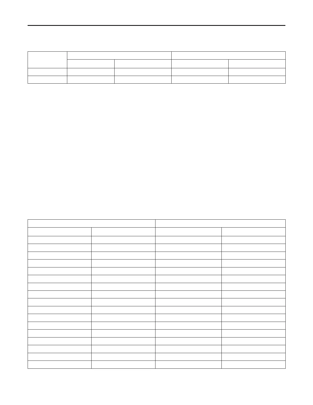
Table 12. POE Oil recharge amount (fl. oz.) (continued)
Tonnage
208/230V 460V
Compressor 1 Compressor 2 Compressor 1 Compressor 2
E/GD*120 43.3 53.1 43.3 53.1
E/GD*150 53.1 43.3 53.1 43.3
2. After the compressor and condenser fan have started
and operated for approximately 30 minutes, observe
the operating pressures. Compare the operating
pressures to the operating pressure curve..
3. Check system subcooling.
4. Repeat Step 1 through Step 3 for each refrigerant
circuit.
5. To stop the SERVICE TEST, turn the main power
disconnect switch to the “Off” position or proceed to the
next component start-up procedure. Remove
electromechanical test mode connections (if
applicable).
Heating Start-Up
When starting the unit for the first time or servicing the
heaters, it is a good practice to start the heater with the
main gas supply turned “Off”. Once the ignition system and
components have been checked, open the main power
disconnect switch to reset the unit.
Final System Setup
After completing all of the pre-start and start-up procedures
outlined in the previous sections (i.e., operating the unit in
each of its modes through all available stages of cooling
and heating), perform these final checks before leaving the
unit:
☐ Inspect the unit for misplaced tools, hardware, and
debris.
☐ Verify that all exterior panels including the control panel
doors and condenser grilles are secured in place.
☐ Close the main disconnect switch or circuit protector
switch that provides the supply power to the unit’s
terminal block or the unit mounted disconnect switch.
Refrigerant Charge and Room
Area Limitations
For more information on refrigerant charge and room area
requirements/limitations refer to “A2L Information,” p. 18.
Table 13. Maximum Refrigerant Charge
A/TA Mmax
ft
2
m
2
lb-oz
kg
40 3.7 2-10 1.2
50 4.6 3-5 1.5
60 5.6 4-0 1.8
70 6.5 4-10 2.1
80 7.4 5-5 2.4
90 8.4 6-0 2.7
100 9.3 6-10 3.0
110 10.2 7-5 3.3
120 11.1 8-0 3.6
130 12.1 8-10 3.9
140 13 9-5 4.2
150 13.9 10-0 4.5
160 14.9 10-10 4.8
170 15.8 11-5 5.1
180 16.7 12-0 5.4
190 17.7 12-10 5.7
200 18.6 13-5 6.0
Start-Up