RT-SVX096A-EN
25
Important: The first 6 inches of supply air plenum and
ductwork must be constructed of sheet metal
as required by NFPA 90B. The supply air
plenum or duct must have a solid sheet metal
bottom directly under the unit with no
openings, registers, or flexible air ducts
located in it. If flexible supply air ducts are
used, they must be located only in the vertical
walls of rectangular plenum, a minimum of 6
inches from the solid bottom. Metal plenum or
duct may be connected to the combustible
floor base; if not, it must be connected to the
unit supply duct exposed to the supply air
opening from the downflow unit.
Main Electrical Power Requirements
☐ Verify that the power supply complies with the unit
nameplate specifications.
☐ Inspect all control panel components; tighten any loose
connections.
☐ Connect properly sized and protected power supply
wiring to a field-supplied/ installed disconnect switch
and to the main power terminal block in the unit control
panel.
☐ Install proper grounding wires to an earth ground.
Note: All field-installed wiring must comply with NEC and
applicable local codes.
WARNING
Hazardous Voltage!
Failure to follow instructions below could result in
death or serious injury.
Disconnect all power to unit before installing or
servicing. More than one disconnect switch may be
required to de-energize the equipment.
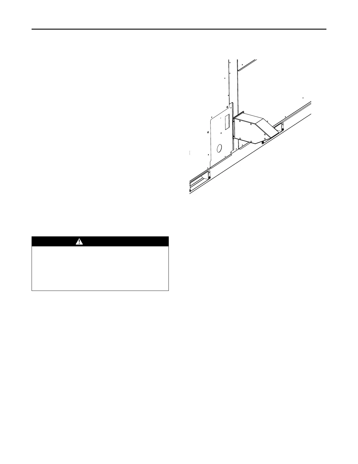
External Vent Hood Installation
1. Remove and discard the cover plate located on the gas
heat panel.
Important:
• Make sure you read the label located
on the cover plate before you discard
it.
• Do not discard the fastening screws!
They will be needed to install the vent
hood.
Figure 10. Vent hood installation
Note: Vent hood image above is for reference only. Please
make the object as the standard and verify it
functions to prevent rain and foreign bodies. It
should not be changed without consultation.
Condensate Drain Configuration
An evaporator condensate drain connection is provided on
each unit. Refer to “Dimensional Data,” p. 11 for the
appropriate drain location.
Note: Use 1-inch PVC pipe to connect to the drain pan
outlet provided in the unit. This is a slip fit joint (no
threads). Do not use PVC glue to connect
condensate drain, thread sealing compound or
Teflon tape may be used.
A condensate trap must be installed at the unit due to the
drain connection being on the negative pressure side of the
fan.
A condensate drain line must be connected to the P-Trap.
Pitch the drain lines at least 0.5-inch for every 10 feet of
horizontal run to assure proper condensate flow. Do not
allow the horizontal run to sag causing a possible
doubletrap condition which could result in condensate
backup due to air lock.
Filter Installation
Each unit ships with 2-inch filters installed. The quantity of
filters is determined by unit size. Access to the filters is
obtained by removing the filter access panel.
Note: Do not operate the unit without filters.
Installation