RT-SVX069D-EN
9
Dimensional Data
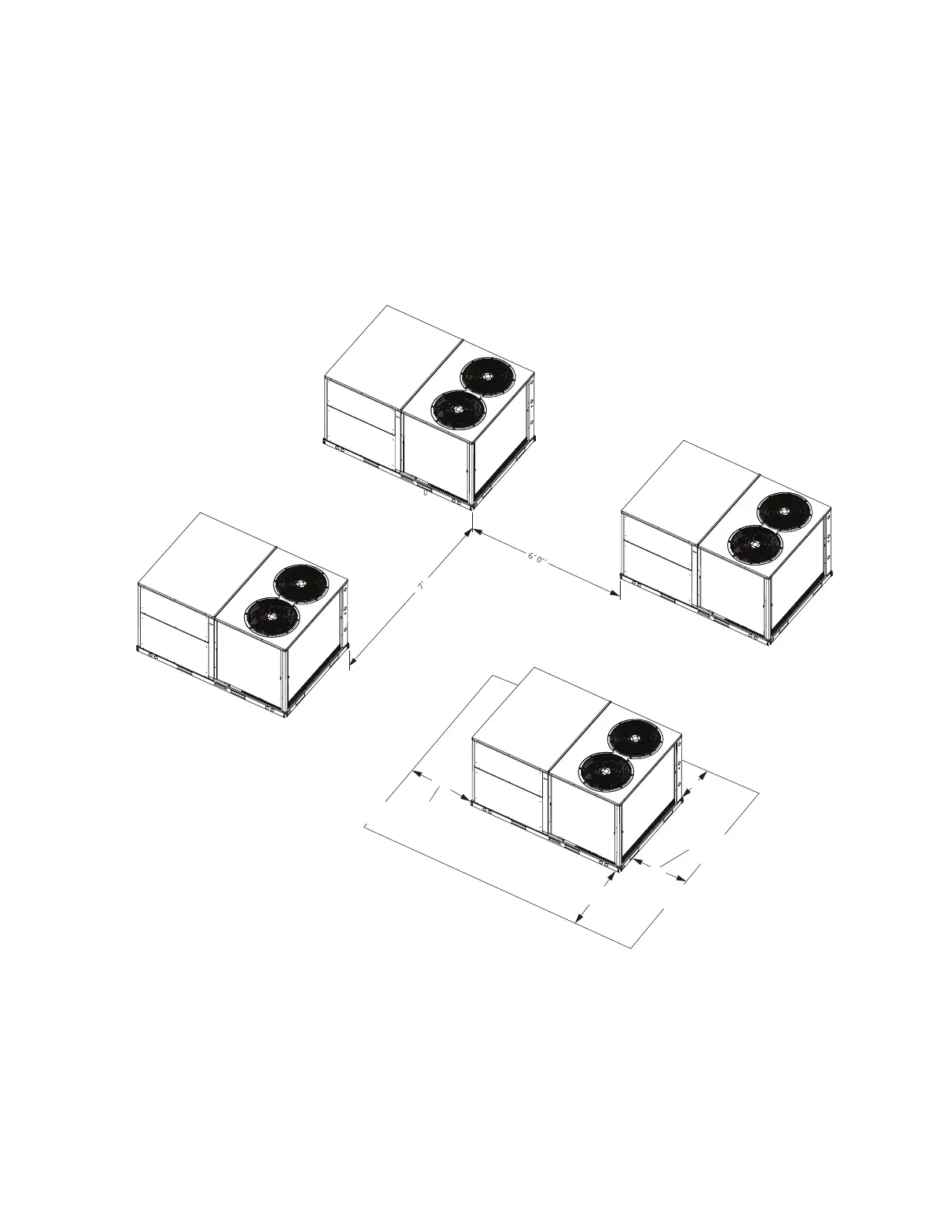
Below figure illustrates the minimum operating and service
clearances for either a single or multiple unit installation.
These clearances are the minimum distances necessary to
assure adequate serviceability, cataloged unit capacity, and
peak operating efficiency.
Providing less than the recommended clearances may
result in condenser coil starvation, “short-circuiting” of
exhaust and economizer airflows, or recirculation of hot
condenser air.
Figure 1. Typical installation clearance for single and multiple unit applications (in inches)
NOTE 1
4’ 0”
1’ 6” Minimum clearance
3’ 0” Side condensate drain is used
1’ 6” Recommended service clearance
4’ 0” Unit disconnect is mounted on panel
SINGLE UNIT
END TO END
NOTE 2,3
SIDE BY SIDE
NOTE 2
5’ 0” WITH ECONOMIZER
3’ 0” WITHOUT ECONOMIZER
NOTES:
1.FOR HORIZONTAL DISCHARGE UNIT,
THIS MEASURE IS REDUCED TO 1’ 6”
TO MINIMIZE DUCT EXTENSIONS.
2.WHEN EQUIPPED WITH ECONOMIZER
OR BAROMETRIC RELIEF DAMPER,
CLERANCE DISTANCE IS TO BE
MEASURE FROM PROTRUDING HOOD
INSTEAD OF BASE.
3.CLEARANCE IS THE SAME IF ANY
UNIT IS ROTATED 180
3.ADDITIONAL CLEARANCE REQUIRED
WHEN BAROMETRIC DAMPER OR
ECONOMIZER IS INSTALLED.
0

 Loading...