20 GECA-SVX01B-EN
Installation
Instructions
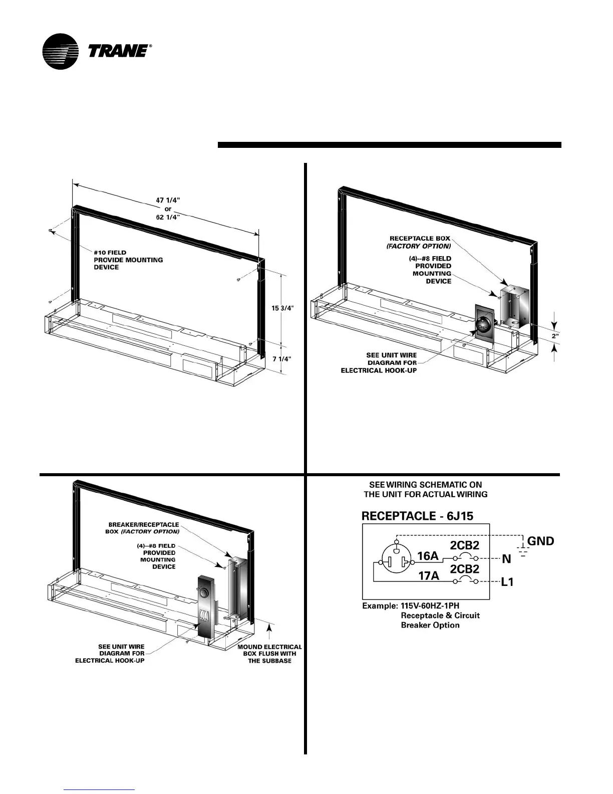
Wall Flange
After removing chassis from the subbase, install the
wall flange assembly to the desired wall with the use
of four #10-field provided screws. The wall flange as-
sembly includes four, 1/4-inch in diameter clearance
holes.
Mounting of Disconnect
(circuit breaker-OPTION)
Mounting of the circuit breaker/receptical box should
be made prior to piping and electrical hook-up. This
factory disconnect option is designed to fit inside the
end pocket. Mount the electrical box flush with the
subbase with four, #8-field supplied screws.
5 6
Mounting of Disconnect
(receptical box-OPTION)
Mounting of the receptical box should be made prior
to piping and electrical hook-up. This factory discon-
nect option is designed to fit inside the end pocket.
Mount the receptical box 2-inches above the top of the
subbase with four, #8-field supplied screws.
7
8
Wiring of Disconnect
(OPTION)
Power wiring to the equipment should be installed per
national and local electric codes by a professional
electrician.
Power wiring to the disconnect may be done at this
time. See the unit’s wiring schematic for field wiring.
The above schematic is for REFERENCE ONLY.