30 WSHP-PRC001-EN
Central Pumping System
Units that employ a central pumping
system contain single or dual pumps
to fulfill pumping requirements for the
entire building system.
The central system’s supply and re-
turn lines should be sized to handle
the required flow with a minimum
pressure drop.
The water-source heat pump (in this
case a high efficiency GEH) may in-
clude add-on accessories to help aid in
system balancing, acoustics and safe-
ty requirements. Some of these items
may be ordered from the factory, then
field installed. Many are provided by
the contractor.
Hose kits are used to connect the
water supply and return line to the
water inlets and outlets. Trane of-
fers various hose kit combina-
tions to better facilitate
system flow balancing.
These flexible hoses also aid
in the reduction of vibration
between the unit and the rig-
id central piping system.
A two position isolation valve is
often applied to systems which in-
corporate variable frequency
pumping. This valve is capable of
stopping/starting water flow to the
unit, which in-turn reduces
the pumping requirements
for the entire system.
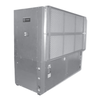
The unit’s (item 2) 3/4-inch high
voltage and (item 3) 1/2-inch low
voltage connections are located
on the left chamfered corner
of the unit. They are de-
signed to accept con-
duit.
A field supplied line voltage dis-
connect should be installed for
branch circuit protection. Check
local codes for requirements.
The central system supply and
return lines should be sized to
handle the required flow with a
minimum pressure drop.
Note: Pipe will sweat if low tem-
perature water is below the dew
point of the surrounding space.
Trane recommends that these
lines be insulated to prevent dam-
age from condensation when con-
denser loop is designed to be
below 60 F.
For acoustically sensitive areas, a
six-inch deep fiberglass insula-
tion is recommended to be field
installed below the horizontal unit.
This field supplied insulation
should be approximately twice the
footprint size of the unit. It pro-
vides sound damping of the unit
while in operation.
Application
Considerations
1
2
3
4
6
5

 Loading...