WSHP-SVX01AA-EN
59
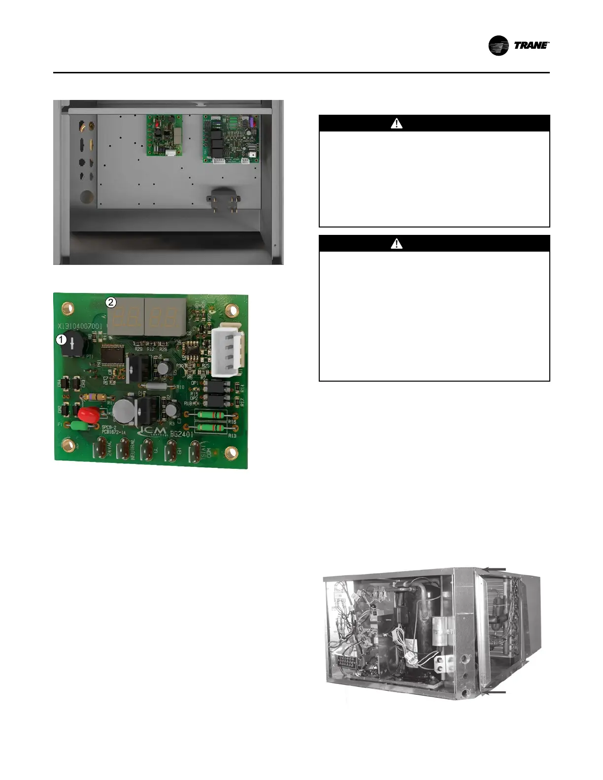
Figure 62. ECM control box
Figure 63. ECM control board
1. Potentiometer will be used to adjust the PWM
output
2. Seven segment display
Using a screwdriver, the potentiometer will be used to
adjust the PWM output from 20% to 100% PWM.
Increasing the PWM will increase the motor speed.
When setting the airflow for air balancing, the high-
speed terminal (GH) must have 24 Vac signal. This will
ensure that the PWM output will be adjusted for the full
load airflow.
The display will show the commanded motor speed
percentage. If running on low speed (GL), the low-
speed value will be displayed. If running in GH the
high-speed value will be displayed. If both GH and GL
input signals are present, the PWM output value will be
the GH value.
Waterside Economizer
Installation
WWAARRNNIINNGG
HHaazzaarrddoouuss VVoollttaaggee!!
FFaaiilluurree ttoo ddiissccoonnnneecctt ppoowweerr bbeeffoorree sseerrvviicciinngg ccoouulldd
rreessuulltt iinn ddeeaatthh oorr sseerriioouuss iinnjjuurryy..
DDiissccoonnnneecctt aallll eelleeccttrriicc ppoowweerr,, iinncclluuddiinngg rreemmoottee
ddiissccoonnnneeccttss bbeeffoorree sseerrvviicciinngg.. FFoollllooww pprrooppeerr
lloocckkoouutt//ttaaggoouutt pprroocceedduurreess ttoo eennssuurree tthhee ppoowweerr
ccaann nnoott bbee iinnaaddvveerrtteennttllyy eenneerrggiizzeedd.. VVeerriiffyy tthhaatt nnoo
ppoowweerr iiss pprreesseenntt wwiitthh aa vvoollttmmeetteerr..
WWAARRNNIINNGG
PPrrooppeerr FFiieelldd WWiirriinngg aanndd GGrroouunnddiinngg
RReeqquuiirreedd!!
FFaaiilluurree ttoo ffoollllooww ccooddee ccoouulldd rreessuulltt iinn ddeeaatthh oorr
sseerriioouuss iinnjjuurryy..
AAllll ffiieelldd wwiirriinngg MMUUSSTT bbee ppeerrffoorrmmeedd bbyy qquuaalliiffiieedd
ppeerrssoonnnneell.. IImmpprrooppeerrllyy iinnssttaalllleedd aanndd ggrroouunnddeedd
ffiieelldd wwiirriinngg ppoosseess FFIIRREE aanndd EELLEECCTTRROOCCUUTTIIOONN
hhaazzaarrddss.. TToo aavvooiidd tthheessee hhaazzaarrddss,, yyoouu MMUUSSTT ffoollllooww
rreeqquuiirreemmeennttss ffoorr ffiieelldd wwiirriinngg iinnssttaallllaattiioonn aanndd
ggrroouunnddiinngg aass ddeessccrriibbeedd iinn NNEECC aanndd yyoouurr llooccaall//
ssttaattee//nnaattiioonnaall eelleeccttrriiccaall ccooddeess..
FFoorr HHoorriizzoonnttaall 00..55--55 ttoonn uunniittss
The following steps were sequenced to aid in the
installation and mating of a water side economizer to a
0.5–5 ton horizontal water-source heat pump.
1. Remove the control side service panel of the water-
source heat pump unit.
2. Remove rubber isolation grommets from the
return-air section. Place them in a convenient
location.
3. Attach ducted panel to the water-source heat pump
unit with six factory provided screws. This panel is
shipped loose with the water-source heat pump but
must be field installed to the unit.
Figure 64. Step 3
IInnssttaallllaattiioonn