WSHP-SVX01AA-EN
61
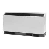
Figure 69. Step 8
9. Wire-tie the sensor to the water SUPPLY side of the
piping (ON, or BEFORE) the 2-position valve. Refer
the figure below.
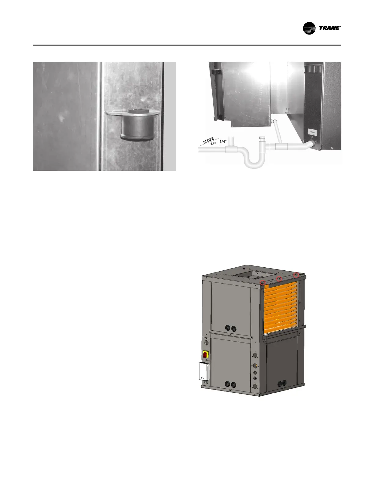
Figure 70. Step 9
10. Bundle excess sensor wire, and wire tie the bundle
neatly. Refer the figure below.
Figure 71. Step 10
11. Thread the valve’s wire lead through the low
voltage hole of the heat pump. Refer the figure
below.
Figure 72. Step 11
12. Wire the valve to the terminal strip according to the
unit wire diagram located on the service control
panel.
RED = 1TB1-14
BLK = 1TB1-18
WHT = 1TB1-15
IInnssttaallllaattiioonn