62
WSHP-SVX01AA-EN
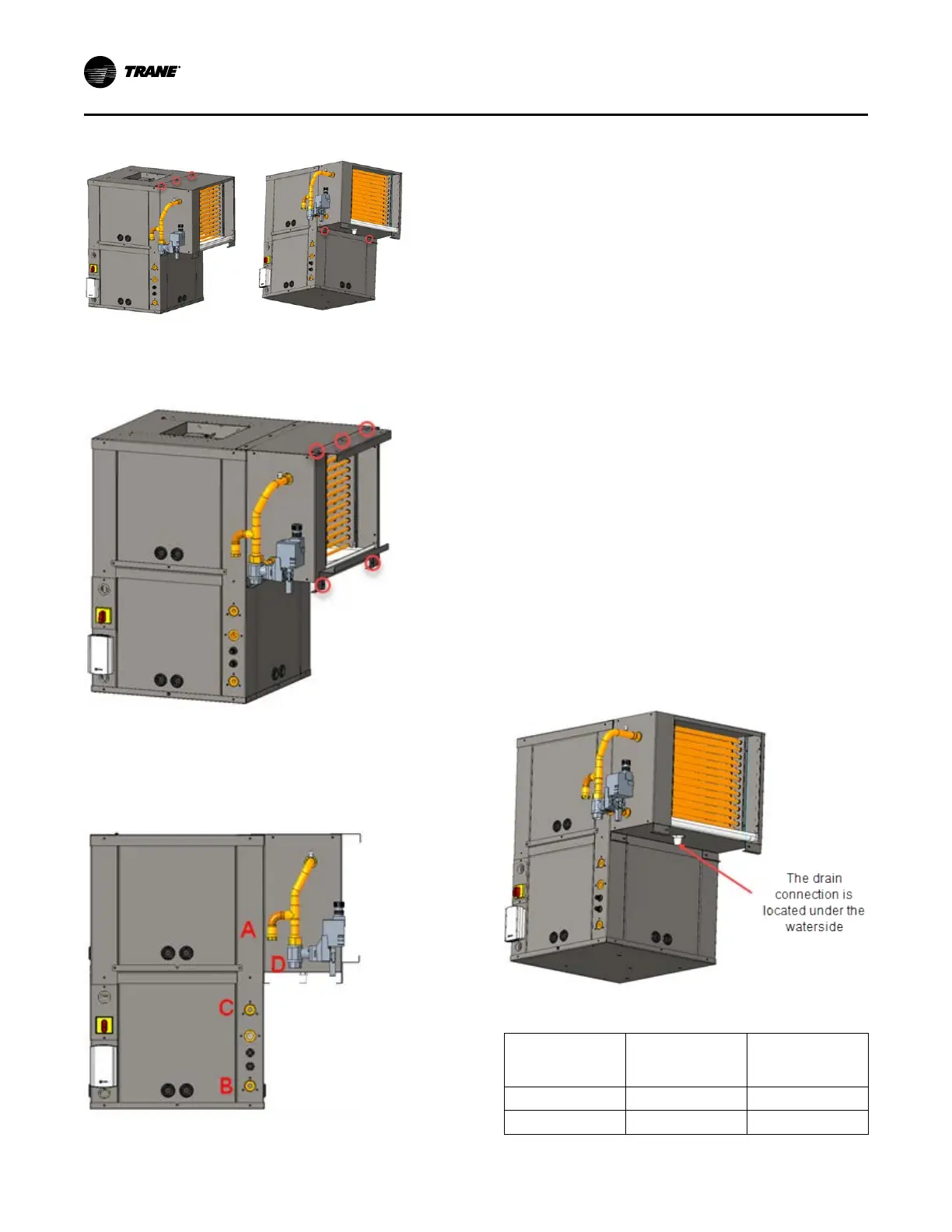
Figure 73. Step 12
13. Bundle excess valve wire, and wire tie the bundle
neatly.
Figure 74. Step 13
14. Install control side service panel.
15. Install the hanging isolation grommets (refer the
figure below) into the hanging brackets The unit
isolators were located in the return-air section of
the unit. See Step 2. Isolators for the economizing
package are located with the economizer.
Figure 75. Step 15
16. Insulate the economizing piping package and the
supply/return/by-pass hoses (3-hoses) via field
provided pipe insulation. Insulating the piping will
stop condensation from forming on the pipe and
dripping onto the ceiling tiles.
NNootteess::
• Trane does not provide insulation on the
economizing piping package. This insulation
must be field provided and field installed.
• Trane does not provide condensate
overflow protection of the waterside
economizer. This must be field provided and
installed.
17. Install filter rack (top and bottom) to the
economizing package. The filter rack is located in
the unit’s packaging along with the filter.
18. Hang unit. See Figure 51, p. 50for hanging of the
packaged unit. Bottom screws referenced in Step 4
must be installed at this time.
19. Field pipe the drain lines of the waterside
economizer and water-source heat pump together
prior to installing a condensate trap (see
“Condensate Drain Connection,” p. 50)for proper
trapping of condensation.
IInnssttaallllaattiioonn
 Loading...


