The Trane Chilled Water Fan Coil, available in HFCC 400-1,200 CFM and HFCD 1,400-2,000 CFM models, is designed for cooling applications in ceiling and ducted installations. This installation manual provides a comprehensive guide for proper setup, operation, and maintenance, emphasizing safety and adherence to local codes.
Function Description
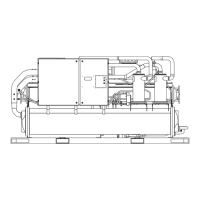
The Trane Chilled Water Fan Coil units are designed to provide cooling by circulating chilled water through a coil, which then cools the air circulated by a fan. These units are specifically engineered for cooling-only operation and are suitable for underceiling installations in both ceiling and ducted configurations. The system relies on a chilled water supply to absorb heat from the indoor air, effectively lowering the room temperature.
Important Technical Specifications
Models and Capacities:
- HFCC Series: 400 - 1,200 CFM (Cubic Feet per Minute)
- HFCD Series: 1,400 - 2,000 CFM
Coil Connections:
- HFCC Models: 5/8 inch copper tube
- HFCD Models: 3/4 inch copper tube
- Water inlet is on the lower tube of the header, and the water outlet is on the upper tube.
Condensate Drain Connections:
- 1/2 inch PVC pipe (or flexible pipe) connection.
- The drain piping must slant downward with a slope of at least 1:50 to prevent leakage.
- The drain pipe should run straight down to a level where runoff will not stain the wall.
- Insulation of the drain pipe with foam polyethylene is recommended to prevent damage to the ceiling or furniture.
Duct Connections:
- Minimum 24 gauge galvanized sheet metal duct (supplied by the installer) is required.
- Ducts attach to collars provided at the unit's air outlet and inlet.
- Field-supplied transition fittings should be used if unit duct collars do not match discharge air-grille collars.
- All ductwork must be properly insulated to prevent condensation.
Electrical Specifications:
- Power Supply: 220-240V/1PH/50Hz (as indicated in the wiring diagram).
- Wiring must comply with local codes and wiring diagrams.
- Only copper conductors are to be used for wiring connections. Unit terminals are not designed for other types of wiring.
- The unit nameplate specifies the electrical rating, which must match the available power supply.
Mounting:
- Designed for suspension from the ceiling using threaded rods (furnished by the installer).
- Holes are provided at the top of the units for suspension.
- Units must be mounted level to ensure proper drainage and operation.
- Suspension rods should include upper W 3/8" nuts and W 3/8" lock washers to prevent upward tilting, and lower W 3/8" lock washers and nuts to secure the unit.
Dimensional Data (Examples for HFCC 04-12):
- HFCC 04, 06, 08:
- A: 762 mm (30")
- B: 882 mm (34 3/4")
- C: 946 mm (37 1/4")
- Inlet/Outlet: 15.88 mm (5/8")
- Fans: 2, Motors: 1
- HFCC 10:
- A: 914 mm (36")
- B: 1034 mm (40 1/4")
- C: 1098 mm (43 1/4")
- Inlet/Outlet: 15.88 mm (5/8")
- Fans: 2, Motors: 1
- HFCC 12:
- A: 1067 mm (42")
- B: 1087 mm (42 7/8")
- C: 1251 mm (49 1/4")
- Inlet/Outlet: 15.88 mm (5/8")
- Fans: 2, Motors: 1
Dimensional Data (Examples for HFCD 14-20):
- HFCD 14-16:
- A: 36.06" (916 mm)
- B: 40.70" (1034 mm)
- C: 43.58" (1107 mm)
- D: 35.70" (907 mm)
- E: 39.88" (1013 mm)
- Inlet/Outlet: 3/4" (19.05 mm)
- Fans: 2, Motors: 1
- HFCD 18-20:
- A: 42.08" (1069 mm)
- B: 46.73" (1187 mm)
- C: 49.21" (1250 mm)
- D: 41.73" (1060 mm)
- E: 45.90" (1166 mm)
- Inlet/Outlet: 3/4" (19.05 mm)
- Fans: 2, Motors: 1
Usage Features
Installation Sequence:
- Installation procedures must be performed in the sequence outlined in the manual.
- Adequate space for unit installation and service clearances must be ensured.
- Proper preparation for piping and electrical connections is crucial before installation.
- Consider additional clearance if external accessories are added.
- The supporting structure (ceiling) must be strong enough to support the unit's weight.
Piping Connections:
- Brazing is used for copper tube connections, utilizing a coupling between the fan coil unit's copper tube and the water pipe.
- Ensure copper tubes are tight before brazing to a solder coupling or expanded tube.
Electrical Connections:
- Wiring must be done by qualified personnel in accordance with local codes and the unit's wiring diagrams.
- The wiring diagram decal on each unit provides specific instructions.
- The manufacturer is not responsible for problems caused by unauthorized changes to internal wiring.
Coil Venting:
- A manual air vent is installed at the highest point of the header to release trapped air when water is first introduced into the coil.
- To vent, rotate the knob counter-clockwise 1-2 turns until a steady stream of water appears, then retighten. Pliers can be used if the knob is too tight.
Maintenance Features
General Maintenance:
- Routine maintenance and servicing should be performed by a qualified service technician through a reputable service company.
- Access to the unit for servicing is provided through removable panels in the ceiling.
Installation Checklist for Verification:
- Electrical Connections: Inspect all field wiring connections for cleanliness and tightness. Verify unit ground connection complies with applicable codes.
- Unit Casing: Ensure the unit casing is level and free of tools or debris.
- Duct Outlets: Confirm ductwork connections are complete, and outlets are open and unrestricted.
- Coil Connections: Verify coil connections are complete and tight.
- Condensate Drain Pan: Ensure connections are tight and drainage is unrestricted.
- Fan Assembly: Inspect to ensure all moving parts move freely.
- Filters: Inspect for proper filters, securely installed.
- Cabinet Panels: All cabinet panels must be secured.
Safety Precautions:
- Always disconnect electrical power before servicing the unit to prevent personal injury or death from electrical shock.
- Follow all cautions and warnings in the manual to ensure personal safety and proper unit operation.
- The Trane Company assumes no liability for installations or servicing performed by unqualified personnel.
- Warranty is void if the equipment is modified or repaired without written approval, operating limits are exceeded, or if the control system or electrical wiring is modified. Damage due to inappropriate installation or non-compliance with manufacturer instructions is not covered by warranty.