Do you have a question about the Trane HORIZON ABDA and is the answer not in the manual?
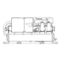
Details the HORIZON® absorption chiller with microprocessor control panel.
Outlines the major sections and their content within the manual.
Explains the basics of the solution cycle and refrigerant/lithium bromide flow.
Describes the function of the condensate heat exchanger for ABTF models.
Explains heating with cooling using a heat exchanger for ABDA models.
Illustrates the single-stage absorption refrigeration cycle.
Details diagnostics and external device feedback during the machine start sequence.
Describes the burner start sequence for ABDA models, including flame safeguard control.
Details events from stop/auto to start, including pump operation and diagnostics.
Describes events from running state through the dilution cycle.
Covers startup pre-heat and shutdown dilution cycle procedures.
Explains the purpose and process of the dilution cycle for crystallization prevention.
Details the normal stop sequence, including burner firing rate and pump operation.
Describes the panic stop procedure and its consequences for chiller operation.
Explains the location and internal hardware components of the chiller control panel.
Details the two sections of the main control panel: control side and power side.
Lists and describes the components within the control panel layout.
Describes the starter module's function for pump operation and AFD interface.
Illustrates the placement of microprocessor control modules within the main and burner control panels.
Illustrates the interrelationship of interprocessor communications (IPC) link.
Controls pump operation and interfaces with AFDs for solution flow.
Manages purge system logic, monitors sensor, and initiates pumpout cycles.
Used to communicate with the chiller module for parameters and data monitoring.
The connection point in the power section for customer three phase power.
Identifies circuit breakers and fuses providing branch circuit protection.
Illustrates the operator interface with its display, LED, and keypad for chiller information.
Describes the operator interface keypad layout and its three key fields.
Details access to status, machine data, setup, service, and diagnostics.
Explains the function of the single red LED for diagnostics and manual service functions.
Guides on selecting group keys for reports and accessing menu items.
Provides steps to create a custom report by selecting desired menu items.
Lists the four preformatted report menus: CUSTOM, CHILLER, CYCLE, and PUMP/PURGE.
Explains how to create and customize reports by selecting up to twenty items.
Lists machine conditions and their corresponding displayed messages during operation.
Identifies active priority and its source for heating/cooling.
Describes the source for chilled water setpoint or evaporator leaving water temperature.
Explains how to navigate through the Cycle Report menu.
Displays the solution temperature leaving the High Temperature Generator.
Provides information on pump or purge hours, starts, and amps.
Details the purge operating modes: Stop, On, and Service Pumpout.
Describes the set points used by the purge module, including operating modes.
Lists inputs for the purge module, such as condenser saturation temperature.
Allows operator to select from four menu groups for settings and parameters.
Explains how to set the purge operating mode (Stop, ON, Service Pumpout).
Defines the priority setpoint source for auxiliary heating.
Specifies the type of hot water reset to be used.
Covers chilled water setpoints and purge control settings.
Allows adjustment of the purge operating mode.
Contains basic setups and feature enables for chiller controls.
Enables or disables keypad and display lockout features.
Provides access to basic setups and feature enables within service settings.
Details printer setup options when a series printer is installed.
Password protected group for chiller field commissioning.
Password protected group for programming unit control module.
Sets the ICS address for Trane BAS systems.
Sets the difference between entering and leaving chilled water temps.
Controls evaporator leaving water temperature.
Adjusts energy input for optimum solution cycle efficiency.
Illustrates the selectable LTSP range for solution flow speed control.
Sets the UCP2 minimum flow output signal in hertz for the LTSP.
Manages energy input for adaptive modes.
Settings for direct-fired heating mode, including delta temperature setpoint.
Manages purge system operation, including pumpout rate and setpoints.
Configures flow display settings for pressure drop curves.
Top level menu for ABDA energy linearization settings.
Uploads adaptive energy linearization coefficients.
Illustrates linear coefficients used with modulating head burners.
Illustrates butterfly valve coefficients for fixed head burners.
Enables or disables the keypad and display lock feature.
Enables or disables the menu settings password feature.
Header for the machine configuration group settings.
Specifies the possible unit types for the chiller.
Option for line voltage sensing if transformers and fuses are present.
Allows external analog signal to adjust chilled water setpoint remotely.
Option for Tracer module communication.
Option for TCI module communication.
Requests password to access the service tools group.
Displays the status of the chilled water pump (Auto or On).
Sets the LTSP solution pump AFD speed command.
Sets the energy input control mode.
Configures differential water pressure sensing options.
Sets the hot water pump control mode to auto or on.
Describes the display sequence when a new diagnostic is detected.
Displays the header screen for active and historic diagnostics.
Provides steps to clear active diagnostics and reset the system.
Explains how to clear informational warnings.
Describes the header screens within the diagnostics menu.
Displays a one-time screen for new diagnostic information.
Details the locations of electrical components and controls for ABDA models.
Diagram showing the location of electrical components on the machine.
Continues the illustration of machine sensor locations.
Diagram showing sensor locations within the absorption fluid cycle.
Identifies sensors, their primary function, and module connection.
Illustrates the locations of machine sensors for ABTF models.
Identifies the evaporator entering water temperature sensor and its reference.
Lists sensors, their primary function, module, and operating range.
Lists sensing points for the single stage Horizon Chiller.
Diagram showing LWT and concentration control inputs to the microprocessor.
Explains LWT control via refrigerant vapor pressure and absorber spray concentration.
Illustrates generator temp, interstage pressure, and low refrigerant temp limits.
Lists functions for adaptive cycle management and their purposes.
Diagram illustrating temperature control monitoring flow results.
Defines the control band around the setpoint where temperature functions are active.
Illustrates leaving water temperature setpoint and LCWTC setpoint range.
Diagram showing concentration control logic and inputs.
Explains how mixed concentration is controlled relative to crystallization line.
Illustrates LTHX margin versus capacity control signal.
Simplified diagram of LWT and concentration control using PID.
Diagram identifying Proportional, Integral, and Derivative functions.
Identifies limit conditions that can override LWT and concentration control.
Illustrates solution flows, sensing, and detection of reverse flow.
Diagram showing electrical connections for SDR system.
Describes the recovery sequence performed by the SDR system.
Explains actions for Reset, Stop, or Panic stop during an SDR cycle.
Illustrates a typical SDR trip temperature and recovery.
Illustrates soft loading time duration and setpoint changes.
Graph showing low tower limit based on saturated condensing temperature.
Shuts down the machine when leaving water temp reaches cutout setpoint.
Illustrates leaving water temperature setpoint and LCWTC range.
Illustrates refrigerant limiting function operation and setpoints.
Illustrates LWT setpoint, differential start, and stop setpoints.
Compares setpoint changes with and without the filtered setpoint feature.
Identifies max differential settings for LWT setpoints without violating other limits.
Composite graph of all settings regarding leaving water temperature control.
Monitors inter-stage pressure for increase to avoid startup diagnostic issues.
Illustrates microprocessor response to increasing interstage pressure.
Graph showing generator solution temperature limits and loading regions.
Limits burner fire rate or turns off burner to reduce generator temperature.
Graph showing exhaust stack limit during automatic operation.
Diagram of the HTC control module and its connections.
Diagram illustrating a typical HTC circuit.
Relates energy input commands to energy valve position.
Graph showing loading regions and temperature limits for hot water generators.
Diagram of the Horizon Purifier Purge system.
Explains how the purge system removes air and non-condensables.
Describes the set points used by the purge module, including operating modes.
Sets the maximum allowable pumpout rate per 24 hours.
Indicates the presence of high liquid refrigerant in the primary purge tank.
Sets the pumpout rate timer and allows manual pumpout entry.
Indicates purge system is running, pumpout disabled.
Initiates pumpout sequence for mechanical repairs, regardless of chiller state.