57
Table 7 identifies unit sensors, primary function control or
monitor, connection points and the normal operation
temperature range of the sensors located in the fluid cycle.
Table 7
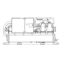
Figure 13
Module
1 Evaporator Leaving Water Temperature 28 - 70 LCWT Control Chiller
Design 44
2 Evaporator Entering Water Temperature 28 - 80 LCWT Control Chiller
Design 54
3 Condenser Leaving Water Temperature 55 - 110 Monitor Chiller
Design 103
4 Absorber Leaving Water Temperature 45 - 100 Monitor Chiller
Design 95
5 Absorber Entering Water Temperature 55 - 110 ELWT-Fdfwd & Chiller
Design 85 Low Tower Limit
6 Entering Heating Hot Water Temperature 120-200 Monitor Burner
(Used for Simultaneous Heat or Cool) Design 130-170
7 Leaving Heating Hot Water Temperature 120-200 Monitor Burner
(Used for Simultaneous Heat or Cool) Design 140-180
8 120 - 200 Concentration Calc Stepper
Design 175 (LTG)
9 Saturated Evaporator Refrigerant Temperature 28 - 60 Evaporator Limit Stepper
Design 38
10 Saturated Condenser Refrigerant Temperature 80 - 180 Concentration Calc Stepper
Design 100 (LTG)
11 Diff Evaporator Water Pressure NA Monitor TBD
12 Diff Tower Water Pressure NA Monitor TBD
13 Interstage Vapor Pressure Transducer 14.9 - 0 PSIG Circuit
15 200 - 320 Concentration Calc Circuit
Design 300 (HTG)
16 Solution Temperature Entering Level Control 120 - 200 Calc Mixed Circuit
(Before Level Control) Design 190 Concentration
17 120 -200 Calc Mixed Circuit
Design 190 Concentration
18 Solution Temperature Entering Absorber 80 - 180 Control T-Margin Stepper
Design 115
19 Solution Temperature Leaving Absorber 80 - 180 Monitor Stepper
Design 100
20 120-20 Monitor Stepper
Design 158
21 Absorber Spray Temperature 80-180 Monitor Stepper
Design 105
22 200-320 Monitor Stepper
Design 270
23 High Flue Gas Temperature Cutout 200-350 Circuit
Design 425
24 Sense Detect Recovery (SDR) Temperature 200 - 320 SDR Circuit
Design 230 Logic
Outdoor Air Temperature (Optional) -20 - 60 Chiller
Design 80
Sensor
Reference
Usable
Range in °F
Sensor Primary
Function
Temperature
Monitor
Chilled Water
Reset Control
High and Low
Pressure Limit
Solution Temperature Leaving Low Temperature
Generator (LTG)
Solution Temperature Leaving High Temperature
Generator (HTG)
Mixed Solution Temperature Entering Low Temperature
Heat Exchanger (LTHX) (After Split)
Solution Temperature at Low Temperature Generator
(LTG) Sprays
Solution Temperature Entering High Temperature
Generator (HTG)
 Loading...