7.1
User interface
7.1.1
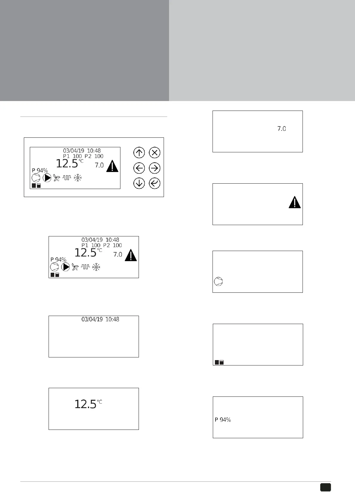
Control panel
Indicates the Set-Point temperature.
Alarm
The control panel enables all machine functions to be performed, to display its operation and any
alarms which may be triggered.
7.1.2
Display
Indicates that a machine operation alarm has triggered.
Compressor
From the display of the control panel it is possible to see the sizes of the values set and machine
operation may be displayed through the LEDs.
Date and time
Indicates compressors operation:
Compressor capacity steps
Indicates the date and time set.
Set water temperature
Indicates the way in which the compressors are distributing.
Requested power
It indicates the outlet water temperature
Set-point
It indicates the power percentage requested by the machine
Pumps
7.
Control Panel
7.1
User interface
7.2
Switch on and off
7.3
Settings
7.4
Unit Status
7.5
Alarms
7.6
Login
7.7
Software
7.8
Electric control information
 Loading...


