21
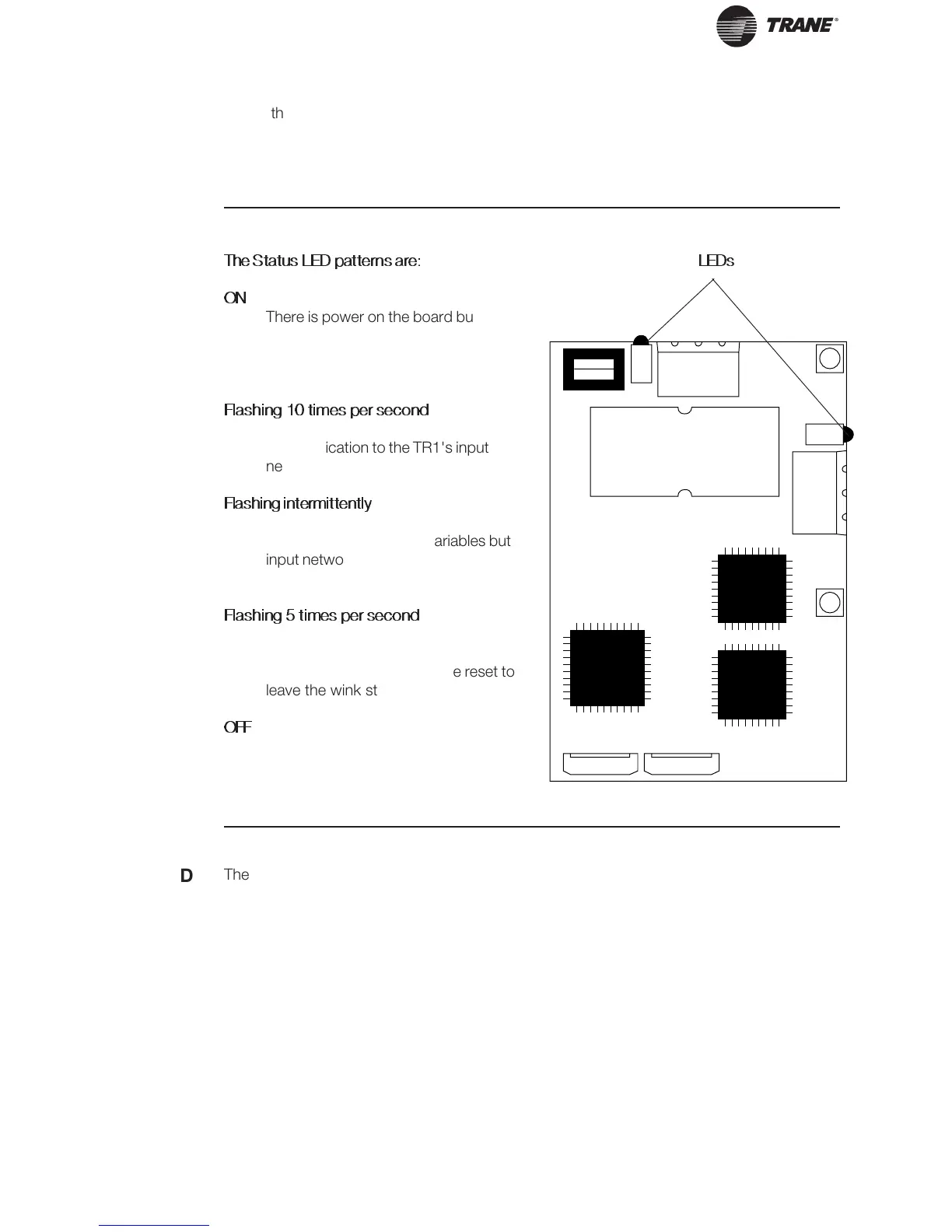
The Status LED patterns are:
ON
There is power on the board but there
has not been any communication to
an input network variable in the last 2
seconds.
Flashing 10 times per second
There is regular network
communication to the TR1's input
network variables.
Flashing intermittently
There is network communication to
the TR1's input network variables but
input network variables are received
at a period greater than 2 seconds.
Flashing 5 times per second
The response to the network
management “Wink” command. The
TR1 LonWorks node must be reset to
leave the wink state.
OFF
No power on board or hardware fault.
LonWorks
Card
Diagnostic
LEDs
The LonWorks board includes two LEDs to
display the communication status of the board,
display the state of the NEURON chip, and
respond to the network management wink
LEDs
command. The onboard LEDs are the Service
LED (LED 1, red) and the Status LED (LED 2,
green).
Status LED
Service LED
The Service LED displays the state of the
NEURON chip. The following table shows the
Service LED patterns for various states and
defines their meaning.

 Loading...