TRANE
R
Installation
7
Foundation
When selecting and preparing the unit
site, follow these guidelines:
1. Ensure that the site can support the
total weight of the unit. Unit weight
figures only provide total gross
weights and do not include the
additional weight for water in any
coils.
2. Confirm that the foundation of the
mounting platform is large enough
to include the unit dimensions plus
service plus service access.
3. The floor or foundation must be
level for correct coil drainage and
condensate flow.
4. Provide adequate lighting for
maintenance personnel to perform
maintenance duties.
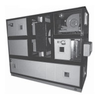
5. When the unit is positioned on site,
there must be sufficient space
around the unit to ensure that correct
operation and effective main-
tenance can be carried out. Figure
6 gives recommended space
allowances.
• On the designated access side of
the unit, working areas must have
minimum 1 mtr, space (P).
• Allowance for coil connections,
dimension “C” must be dimension
200mm + unit width.
• A clear unobstructed area before
and after an air intake or discharge
is required to ensure correct air
movement. The width of the area
must be >= the width of the unit, and
the depth (dimension “L”) must be
>= 0.5 x the overall unit height.
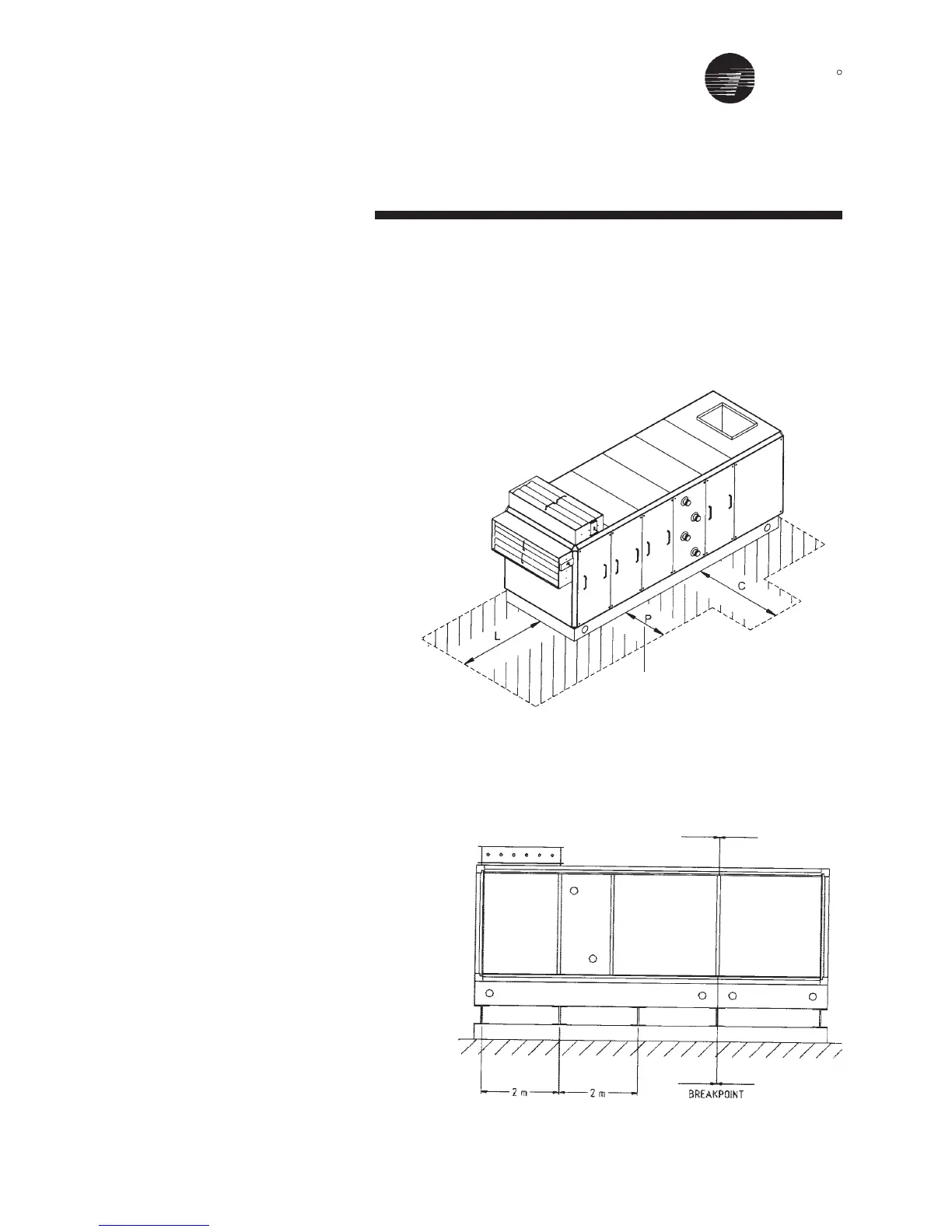
Complete reinforced concrete
foundations are suitable or strip
foundations may also be used (see
Figure 7).
In the case of strip foundations,
concrete or steel supports are
premissible, but support is required
under breakpoints and every 2 m along
the unit base.
Figure 7 - Air Handling Unit Steels Foundation
Figure 6
P = 1 MTR min