TRANE
R
coil as possible. Base filter-
drier selection on a minimum
pressure drop of 2 psi at the design
condition.
1. Install moisture indicator/sight
glass between the expansion valve
and filter-drier. The moisture
indicator/ sight glass must be sized
to match the size of the liquid line at
the thermal expansin valve.
2. Size liquid line shutoff valve with an
access port using the selected liquid
line OD, and install it close to the
condenser.
3. Minimize use of other valves, tube
bends and reducers since these
items tend to increase pressure
drop and to reduce subcooling at
the expansion valve.
4. The Thermal Expansion Valve (TEV)
must be selected for proper size
and capacity. The size of the TEV
should cover the full range of
loadings. Check that the valve will
successfully operate at the lightest
load condition. Select expansion
valves with external equalizer
connections, and those designed
to operate against a back pressure
of 20 pounds per square inch
higher than actual evaporator
pressure.
5. Install the TEV directly in the coil liquid
connection (distributor) provided.
The liquid distributor must be in a
true vertical position.
Suction Line Components
Install suction line pressure tap on the
leaving side of the evaporator coil near
the TEV sensing bulb location.
Accurate superheat measurement and
thermal expansion valve adjustment
demands that suction pressure be
22
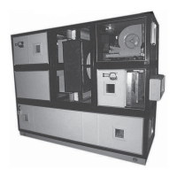
Assembly & Installation
Refrigerant Coil Piping
TYPE FD COILS HAVE BEEN
DEHYDRATED AND CHARGED WITH
A HOLDING CHARGE OF DRY
NITROGEN. 10-20 PSIG TO
PREVENT LEAKS AND SYSTEM
CONTAMINATION, DO NOT BREAK
THE SEALS UNTIL THE COIL IS
INSTALLED.
1. Follow accepted refrigeration piping
practices and safety precautions for
typical refrigerant coil piping and
components.Specific recommen-
dations are provided with the
condensing units, including
instructions for pressure-testing,
evacuation, and system charging.
General recommendations for
component selection and line
sizing follow.
2. Leak-test the entire refrigeration
system after all piping is complete.
3. Charge the unit according to
approximate weight requirements,
operating pressures and super-
heat / subcoling measurements.
4. Adjust the thermal expansion valve
setting if necessary.
General Refrigerant Piping
Recommendations
IMPORTANT: REFER TO THE NOTE
ON THE INSIDE FRONT COVER OF
THIS MANUAL REGARDING
HANDLING OF REFRIGERANTS.
Liquid Line Components
Trane recommends the use of a
properly sized liquid line filter-drier
installed upstream from the expansion
valve and as close to the evaporator
measured near the evaporator coil.
Liquid Line Sizing
All compressors have a Refrigerant
Charge Limit (RCL) that must not be
exceeded. Since the RCL and
pressure drop are in direct conflict with
each other, Trane recommends that the
liquid line be sized as small as
possible, while maintaining a low
enough pressure drop to ensure
5°F(3°C) of subcooling at the
expansion valve.
Suction Line Sizing
Suction line tubes must be sized to
maintain refrigerant vapor velocities
that are high enough to ensure oil
entertainment under all operating
conditions.
It is not necessary to pitch horizontal
suction lines toward the compressor
when refrigerant coils is used with
Trane condensing units that are
designed with a gas trap in the suction
line just prior to the compressor.