Do you have a question about the Trane S9V2B040U3PSBC/D and is the answer not in the manual?
Covers critical warnings for fire, explosion, electrical shock, and carbon monoxide hazards.
Lists all items included in the furnace document package.
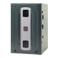
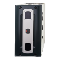
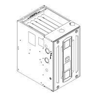
Lists the components and parts of the furnace.
Outlines essential safety measures for furnace installation, servicing, and operation.
Specifies requirements for furnace placement and minimum clearances to combustible materials.
Covers panel removal, horizontal installation, and general guidelines.
Details gas piping, combustion checks, valve adjustment, and high altitude derating.
Covers general venting, special cases, terminations, materials, lengths, and horizontal venting.
Guidelines for duct connections, supply/return, filters, and electrical wiring.
Warns about condensate leaks and recommends drain pan installation to prevent property damage.
Specific instructions for connecting condensate drains for upflow furnaces.
Details condensate drain connection for downflow furnaces with left-side service.
Details condensate drain connection for downflow furnaces with right-side service.
Instructions for condensate drain connections in horizontal furnace installations.
Checks to perform before starting the furnace, ensuring proper installation and readiness.
Step-by-step guide for initiating furnace operation and verifying component function.
Procedures for checking and adjusting furnace limit switches and safety controls.
Instructions on how to test the proper operation of furnace limit switches.
Illustrates approved venting options and tables for upflow, horizontal, and downflow furnace models.
Instructions for top and left side vented combustion air for upflow furnaces.
Instructions for top and side vented combustion air for horizontal upflow furnaces.
Instructions for top and side vented combustion air for downflow furnaces.
Table showing default and adjustable gas heating CFM values for different furnace models.
Explains the meaning of various status codes displayed on the IFC's seven-segment LED.
Procedure for entering and using the Run Test Mode to verify component operation.
Instructions on how to view, clear, and reset fault codes and factory defaults.
Lists and explains various alarm and error codes generated by the furnace control board.
Diagram of IFC components and initial startup/troubleshooting steps.
Detailed flowcharts for diagnosing specific fault codes (2.1, 2.2, 2.3, 3.1, 3.2, 3.3, 3.4, 04, 05, 06).
Explains the timing of EAC and HUM relays during furnace operation.
Detailed sequence for initiating and operating the furnace in 1st stage heating mode.
Step-by-step process for single-stage cooling operation.
Step-by-step process for two-stage cooling operation.
| Model | S9V2B040U3PSBC/D |
|---|---|
| Type | Gas Furnace |
| Brand | Trane |
| Efficiency Rating | High Efficiency |
| Heating Capacity | 40, 000 BTU |
| BTU Input | 40, 000 BTU |
| Blower Type | Variable Speed |
| Blower Motor Type | ECM |
| Ignition Type | Hot Surface Ignition |
| Stages | Two-Stage |
| Voltage | 120V |
| Gas Type | Natural Gas |
| Warranty | 10 Years |


 Loading...