Do you have a question about the Trane S9V2B040U3VSAE and is the answer not in the manual?
Covers warnings related to fire and explosion risks from gas leaks and improper handling of flammable materials.
Addresses risks of electrical shock, fire, and explosion due to improper servicing or wiring.
Highlights hazards of carbon monoxide poisoning from improper venting or damaged components.
Covers warnings for installation, high voltage, moving parts, and overheating hazards.
Details cautions for freeze protection, ignition function, water damage, voltage, corrosion, and sharp edges.
Lists the contents of the document pack included with the S9V2-VS furnace.
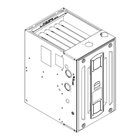
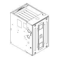
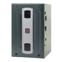
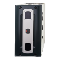
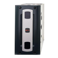
Provides a list of all components included in the furnace.
Outlines essential safety practices and precautions for furnace installation, servicing, and operation.
Provides general recommendations for furnace installation, including code compliance and handling.
Specifies requirements for furnace location and clearances to combustible materials.
Instructions for removing the furnace access panel using specific tools.
Guidelines for installing the furnace horizontally in attics or crawl spaces.
Procedure for installing the furnace in a hanging position using straps.
Details on connecting the gas supply, including pipe types and shut-off valves.
Procedure for checking combustion and input rates using gas flow tables.
Instructions for adjusting the manifold pressure for natural gas and propane.
Guidance on adjusting furnace input rating for installations above sea level.
Requirements for furnace venting, emphasizing positive-pressure systems and material compatibility.
Instructions for specific venting scenarios, including condensate prevention in air intake.
Guidelines for direct and non-direct vent termination locations and configurations.
Details on materials and methods for attaching vent piping, including joint sealing.
Procedure for cementing PVC pipe joints for venting systems.
Lists approved materials and standards for vent pipe fittings.
Provides maximum allowable equivalent vent lengths based on model, pipe size, and altitude.
Specific instructions for horizontal venting applications, including pipe slope and insulation.
Guidance on venting through walls using concentric vent kits.
Specifies required clearances for horizontal vent terminals from building features.
Details clearances for non-direct vent terminations in Canadian and US installations.
Details clearances for direct vent terminations in Canadian and US installations.
Instructions and diagrams for venting the furnace through the roof.
Guidelines for routing vent piping through unused masonry chimneys.
Instructions for downward venting configurations and condensate trap requirements.
Requirements for adequate airflow for combustion and ventilation in confined and unconfined spaces.
General guidelines and considerations for connecting air ducts to the furnace.
Details on connecting supply ducts to the furnace, including coil requirements.
Specific requirements for drain pan shields and suitability for coils installed on furnaces.
General rules for return duct connections, including disallowed configurations and sealing.
Information on typical upflow return air filter installations and preparation.
Instructions for making electrical connections to the furnace, emphasizing polarity.
Wiring diagrams for connecting thermostats to the furnace for various heating/cooling modes.
Wiring details for communicating controls with non-communicating furnaces and VS cooling/HP.
Instructions for installing condensate drains in vertical furnace applications.
Steps for connecting the condensate drain for downflow furnaces with left side condensate.
Steps for installing the condensate drain for downflow furnaces with right side condensate.
Recommendations for auxiliary drain pans and condensate drainage in horizontal installations.
Ensures all connections, filters, and venting are correct before initial startup.
Guides for checking unit operation through a complete cycle.
Procedures for checking and adjusting limit switches for safe operation.
Venting options for upflow furnaces with combustion air exhausted through the top or side.
Venting options for horizontal left furnaces with combustion air exhausted through the top or side.
Venting options for horizontal right furnaces with combustion air exhausted through the top or left.
Venting options for downflow furnaces with combustion air exhausted through the top or left.
Instructions for top venting combustion air on upflow furnaces in upflow position.
Instructions for modifying upflow furnaces for left side combustion air venting.
Instructions for top venting combustion air on upflow furnaces in horizontal left position.
Instructions for modifying upflow furnaces for side venting of combustion air in horizontal left position.
Instructions for top venting combustion air on upflow furnaces in horizontal right position.
Instructions for modifying upflow furnaces for left side venting of combustion air in horizontal right position.
Instructions for top venting combustion air on downflow furnaces.
Instructions for modifying downflow furnaces for side venting of combustion air.
Specifies the distance from the belly band to the motor face for minimum vibration.
Lists and explains the various display codes used by the IFC.
Guides for viewing, clearing, and resetting fault codes.
A table listing error codes, their explanations, and potential causes.
Diagram showing the layout of components on the Integrated Furnace Control (IFC).
Initial diagnostic steps for troubleshooting IFC issues.
Troubleshooting flow for fault code 01, indicating an internal IFC failure.
Troubleshooting flow for fault code 2.1, related to retry lock out for ignition.
Troubleshooting flow for fault code 2.2, related to recycle lock out for flame loss.
Troubleshooting flow for fault code 2.3, indicating gas valve issues.
Troubleshooting flow for fault code 2.4, related to redundant relay (HLO) issues.
Troubleshooting flow for fault code 3.2, related to PS1 pressure switch issues.
Troubleshooting flow for fault code 3.3, indicating PS2 pressure switch closed when it should be open.
Troubleshooting flow for fault code 3.4, indicating PS2 pressure switch open when it should be closed.
Troubleshooting flow for fault code 04, related to flame rollout issues.
Troubleshooting flow for fault code 05, indicating flame sensed when it should not be.
Troubleshooting flow for fault code 06, indicating reversed high voltage polarity.
Troubleshooting flow for fault code 06, indicating a faulty ground connection.
Troubleshooting flow for fault code 6.3, related to igniter relay or circuit issues.
Troubleshooting flow for fault code 7.1, indicating external gas valve circuit errors.
Troubleshooting flow for fault code 7.2, indicating internal control board errors with HLO relay.
Troubleshooting flow for fault code 08, indicating low flame sense current.
Troubleshooting flow for fault code 09, related to condensate pressure switch or inducer limit errors.
Troubleshooting flow for fault code 10, indicating communication errors between components.
Troubleshooting flow for fault code 11, indicating gas valve relay failures or 24VAC at the gas valve.
Troubleshooting flow for fault code 12, indicating an open or missing onboard 5 amp fuse.
Troubleshooting flow for fault code 13, related to blower motor HP or ID mismatches.
Troubleshooting flow for fault code 14, indicating missing or unreadable PM information.
Troubleshooting flow for fault code 15, indicating corrupted PM and IFC information.
Troubleshooting flow for fault code 17, indicating IFC not receiving a return signal from the blower motor.
Troubleshooting flow for fault code 18, indicating IFC does not see a send message.
Diagnostic steps for troubleshooting serial motor issues.
Detailed sequence for 1st stage gas heating operation.
Detailed sequence for 2nd stage gas heating operation.
Detailed sequence for single stage cooling operation.
Detailed sequence for two stage cooling operation.
Explanation of the inducer learning routine for optimizing speed.
Specifics of the inducer learning routine for 1st stage heat.
Specifics of the inducer learning routine for 2nd stage heat.
Annual checks for flue products, vent connectors, duct connections, and furnace support.
Recommendations for filter cleaning or replacement frequency.
Guidelines for blower motor bearing lubrication and annual cleaning.
Information on the hot surface igniter and handling precautions.
Instructions for annual burner cleaning and addressing yellow flames.
Annual inspection for corrosion/deterioration and cleaning of flue gas passages.
Checks for condensate drain blockage to prevent water damage.


 Loading...