S9V2-SVX001-1A-EN
93
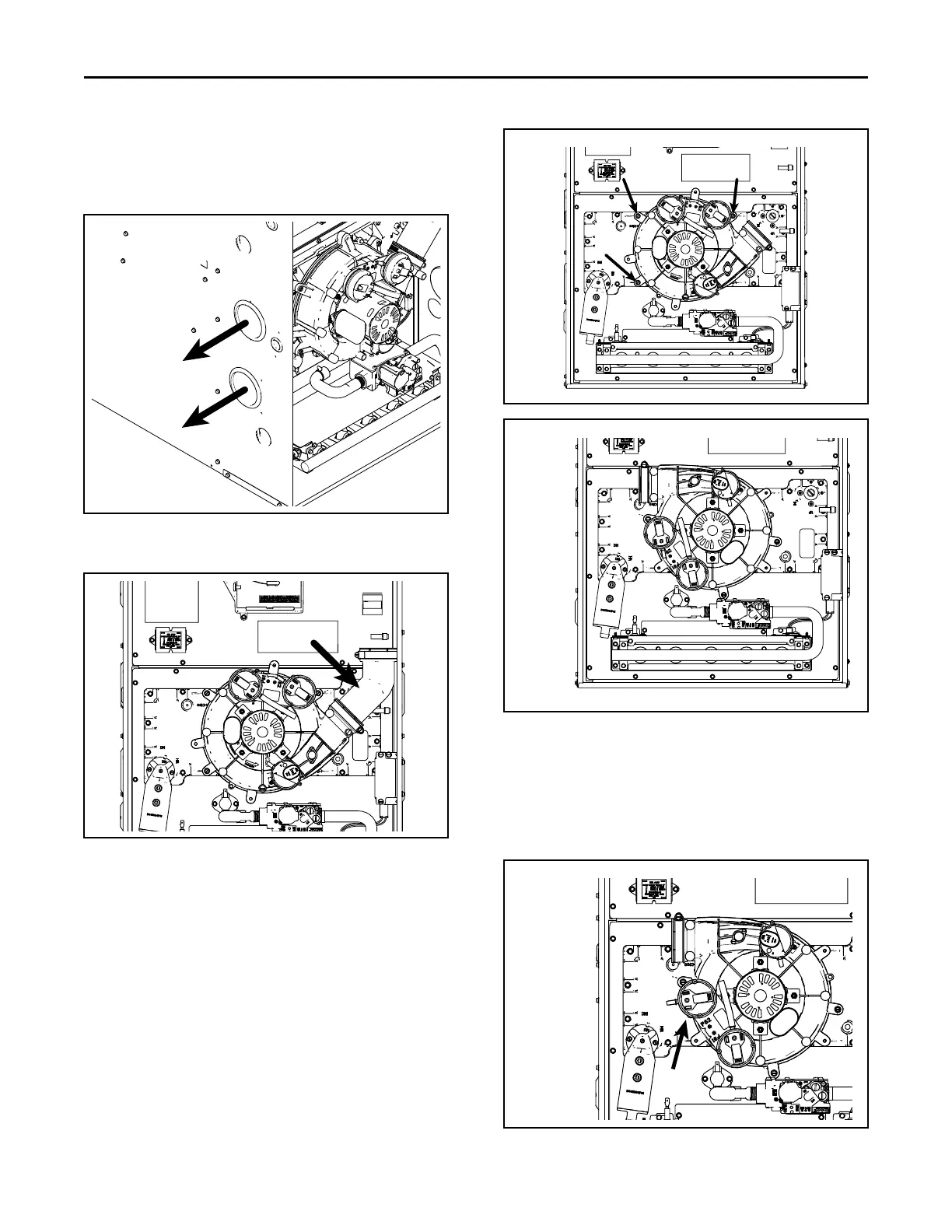
6. Remove two 3” plugs on left side of cabinet. To be
used for combustion air exhaust and inlet.
7. Reuse the two 3” plugs to seal the two 3” default
openings on the top of the cabinet.
8. Loosen the clamp holding the 45° elbow. Remove
the elbow and discard.
9. Remove the three inducer mounting screws.
10. Rotate inducer counterclockwise so that the inducer
outlet aligns with the exhaust vent outlet.
11. Reinsert and tighten screws to 30 in.-lbs. Do not
overtighten.
12. Remove the pressure switch bracket assembly.
13. Remove the screw that holds PS2, rotate 90 degrees
counterclockwise, and reattach.
14. Reattach the pressure switch bracket assembly.
NNoottee:: The illustration shows PS2 in its final position
after being rotated.
FFuurrnnaaccee CCoommbbuussttiioonn AAiirr EExxhhaauusstt OOppttiioonnss

 Loading...


