Installation
10 PART-SVN227B-EN
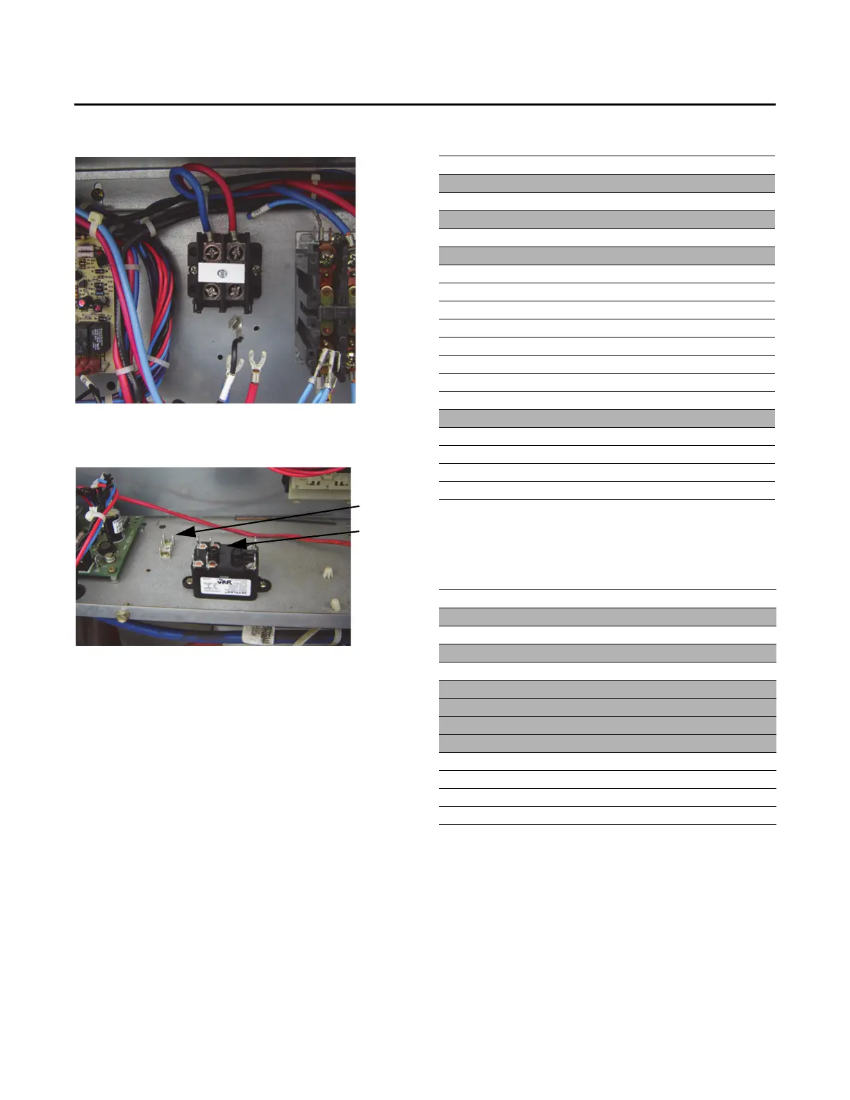
Note: For multispeed conversion the second relay (VSR)
would be installed to the right of the VRR pictured.
Wiring
The tables below contain the connection information for
the control panel wires that ship with the upgrade package
based on the type of upgrade being performed. Directions
and diagrams in the sections to follow will detail the
connections to be made.
Figure 9. Terminal block install
ation
Figure 10. Field installed terminal strip and relay
(SZVAV)
Table 4. Multispeed upgrade wires
Terminal Wire Number Terminal Usage
VRR-3 36CC GTB All
VSR-3 36CD GTB
All
RTRMP1-2 36CF GTB All
PPF7-3 36CG GTB
Electric Heat
GV PPF10-2 36CK GTB Gas Heat
PPF27-1 600B VRR-2 All
PPF27-2 601B VRR-4 All
PPF27-3 603B VSR-5 All
PPF27-4 604B VSR-6 All
PPF27-4 604E RESISTOR All
PPF27-6 607C RESISTOR All
RTRM P2-5 608A VSR-1 All
RTRM P9-1 609A RTRM P9-2
All
PHM Y-OUT W38 RTRM P1-12 All
COMM PPF5-5 W63 RTOM PPF8-1 All
COMM PPF5-4 W64 RTOM PPF8-2 All
COMM PPF5-2 W65 RTOM PPF8-3 All
COMM PPF5-1 W66 RTOM PPF8-4 All
Note: -GTB = New terminal strip installed next to communications module
-VRR = New relay
-VSR = New relay (Multispeed Only)
Table 5. New wiring for SZVAV upgrade
Terminal Wire Number Terminal Usage
VRR-3 36CC GTB All
RTOM P12-2 36CE GTB
All
GV 36CK GTB Gas Heat
PPF7-3 36CG GTB
Electric Heat
PPF27-1 600B VRR-2 All
PPF27-2 601B VRR-4 All
PPF27-5 604D RTOM P11-2 All
PPF27-6 607B RTOM P11-1 All
COMM PPF5-5 W63 RTOM PPF8-1 All
COMM PPF5-4 W64 RTOM PPF8-2 All
COMM PPF5-2 W65 RTOM PPF8-3 All
COMM PPF5-1 W66 RTOM PPF8-4 All
Note: -GTB = New terminal strip installed next to communications module
-VRR = New relay
-VSR = New relay (Multispeed Only)