Installation
PART-SVN227B-EN 13
9. The wire harness for W63 through W66 is included
with the wiring kit along with the gender change wire
for units where an RTOM module was previously not
installed. Check the original Control Box Connections
diagram for how to use the gender change wire along
with the W63 through W66 harness to make the
connection from the RTOM J11 to Communications J2
pins. If the unit already had an RTOM and
Communications Module these wires will not be
needed.
Wiring Diagrams
Kit 018600350100 contains the wiring diagrams seen in
Table 7. The electrical and connection schematic diagrams
are common for all units but the electrical control and
power diagrams will need to be selected based on the unit
voltage and the type of heat that the unit has. Control
electrical, power electrical and schematic electrical
diagrams can be stuck over the existing electrical
diagrams on the inside of the control panel cover however
the schematic connection should not be placed over the
existing diagram as it only has wire labels for the wiring
that was changed or added during the conversion.
In addition to the wiring diagrams, affix
the top section of
the name
plate sticker that contains the upgrade order
number and serial number near the original unit
nameplate sticker.
Setting Economizer Damper
Positions
Note: New settings are needed for the economizer
damper position so that the amount of outdoor air
can keep up with the varying fan speed.
For units not configured with demand control ventilation
(DCV),
additio
nal minimum position setpoints to increase
outdoor airflow accuracy is supported; directions for
setting damper positions with DCV installed are included
in the DCV installation literature (ACC-SVN16*-EN). The
operation is similar to OA CFM Compensation on
Traditional VAV units, with the addition of a Design
Minimum Position setpoint at Middle Fan Speed
Command. The following setpoint potentiometers will be
used on the RTEM:
1. Design Min at Minimum Fan Speed Command (RTEM
DCV Min)
2. Design Min at Middle Fan Speed
Command (RTEM
DCV Setpoint LL)
3. Design Min at Full Fan Speed Command (RTEM Design
Min)
The contro
ller calculates the a
ctive
OA Damper Minimum
position between the user-selected setpoints based on the
supply fan speed command. By default, the Design
Minimum Position schedule is a linear line through all user
selectable Design Minimum Position setpoints. As with
Demand Controlled Ventilation, if the Design Minimum
Position at Middle fan speed command is set to a point that
would be higher than the calculated linear line between
the Design Minimum Position setpoints at Minimum and
Maximum fan speed command, the minimum position is
limited to the point that would make the Design Minimum
Position schedule linear.
Provisions have been made in Service Test Mode to allow
fo
r prope
r damper minimum position setup:
1. To set the Design Minimum Position setpoint at
M
inimum Fa
n Speed, set the unit to operate at Step 1
(Fan ON) or Step 2 (Economizer Open) and make the
proper adjustment.
2. To set the Design Minimum Position setpoint at Middle
F
an Spe
ed, set the unit to operate at Step 3 (Cool 1) and
make the proper adjustment.
3. To set the Design Minimum Position setpoint at Full
Fan Spe
ed, set the unit to operate at Step 4 (Cool 2) and
make the proper
adjustment.
Zone Sensor
For fully modulating Single Zone VAV operation, a zone
temperature sensor is required. A zone temperature
sensor does not ship with the upgrade kit. Wiring for the
zone temperature sensor is included with the sensor if
purchased separately.
If thermostat control is being replaced b
y the zone sen
sor
to achieve fully modulating single zone VAV operation, it is
possible to reuse the thermostat wires to connect in the
zone sensor. If the unit has been upgraded using the single
zone VAV parts and wiring method found in this manual,
no additional settings are needed for the unit perform as
a single zone VAV unit.
A thermostat will NOT provide fully modulating single
zone VAV contro
l. If the unit has been upgraded using the
single zone VAV parts and wiring but still has thermostat
control, the unit will revert to 2-speed fan control unless a
zone sensor is added.
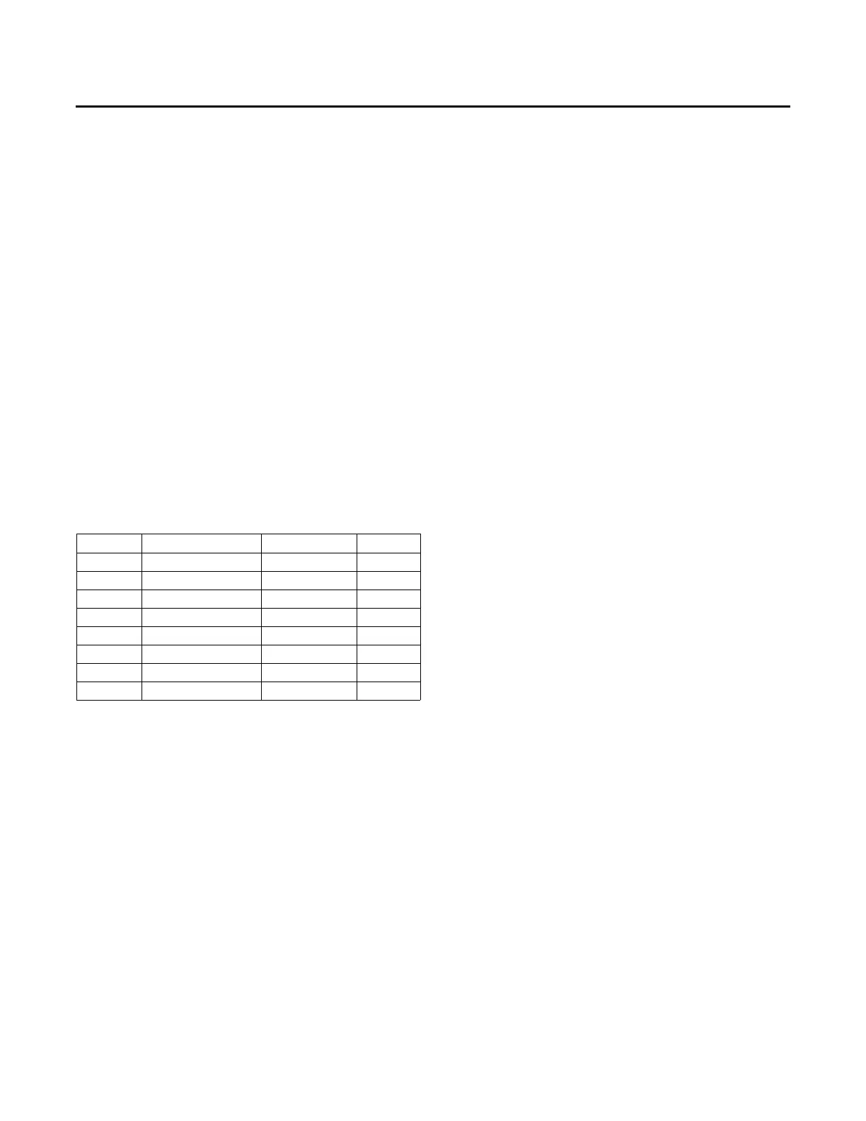
Table 7. Wiring diagrams
(a)
in kit 018600350100
(a) Always refer to the most recent revision of each wiring diagram.
Number Type Heat Voltage
23130064 Control Electrical Electric/None All
23130067 Control Electrical Gas All
23130053 Power Electrical Electric/None 208-230
23130054 Power Electrical Electric/None 460
23130345 Power Electrical Gas 208-230
23130347 Power Electrical Gas 460
23130376 Schematic Electrical All All
01860036 Schematic Connection All All