Installation
PART-SVN227B-EN 9
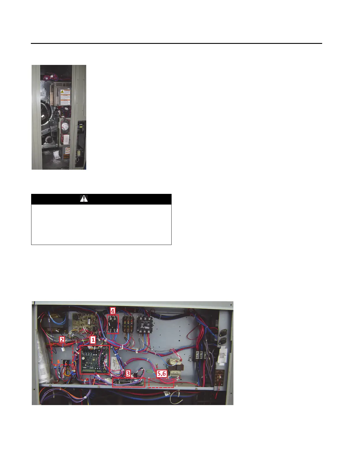
Control Panel Components
1. Remove and replace the existing RTRM module with
the new RTRM module provided. Reconnect all plugs/
wires that were removed from the existing module to
the new module. Refer to the Control Box Connections
diagram when connecting plugs to the module.
2. Remove and replace (or add) the RTOM
module with
the new RTOM module provided. Reconnect all plugs/
wires that were removed from the existing module to
the new module. Refer to the Control Box Connections
diagram when connecting plugs to the module.
3. Communications module location is highlighted in the
pi
cture below. It is not necessary to add or replace the
communications module for the upgrade, it will be
referred to in terms of locating the new ground
terminal and relay(s).
4. Remove and replace the supply fan motor contactor
with the terminal block (HTB3
) prov
ided. There will
most likely not be two existing holes that will line up
with the mounting holes of the terminal block. Use an
existing hole and then using a 1/8-in. drill bit drill a hole
to provide a location for the second screw. Reconnect
wires 1A, 2A, 8A and 9A after the terminal block has
been secured to the back panel. (1A to L1, 2A to L2, 8A
to T1, 9A to T2)
5. *Install the terminal st
rip (GTB
) provided.
6. *Install the relay(s) (VRR, VRS) provided. (For
Multispeed operation both r
elays are needed, for
SZVAV only one relay is needed (VRR).)
7. Replace the Economizer Module (RTEM) if the unit is
eq
uipped
with an economizer. The Economizer
Module is located behind the small access panel on the
outside of the economizer hood.
*Note:I
n units built before single zone VAV or multispeed
was available
from the factory, holes for the GTB,
VRR and VRS will need to be drilled using a 1/8-in.
drill bit. Positioning should be to the right of the
communications module as seen in Figure 10. If the
area to th
e right of the communications module is
not available then use the area to the left of the
communications module.
Figure 7. Factory installed VFD assembly
WARNING
Hazardous Voltage!
Failure to disconnect power before servicing could
result in death or serious injury. Disconnect all electric
power, including remote disconnects before servicing.
Follow proper lockout/tagout procedures to ensure the
power can not be inadvertently energized.
Figure 8. Control panel installation