Installation
8 PART-SVN227B-EN
Discharge Air Sensor
For multispeed or single zone VAV operation a discharge
air sensor is required. A discharge air sensing kit ships
with each upgrade kit. Literature RT-SVN02*-EN ships
along with the discharge air sensor parts kit and should be
referenced for installation of the sensor. If a discharge air
sensor is already installed it does not need to be replaced.
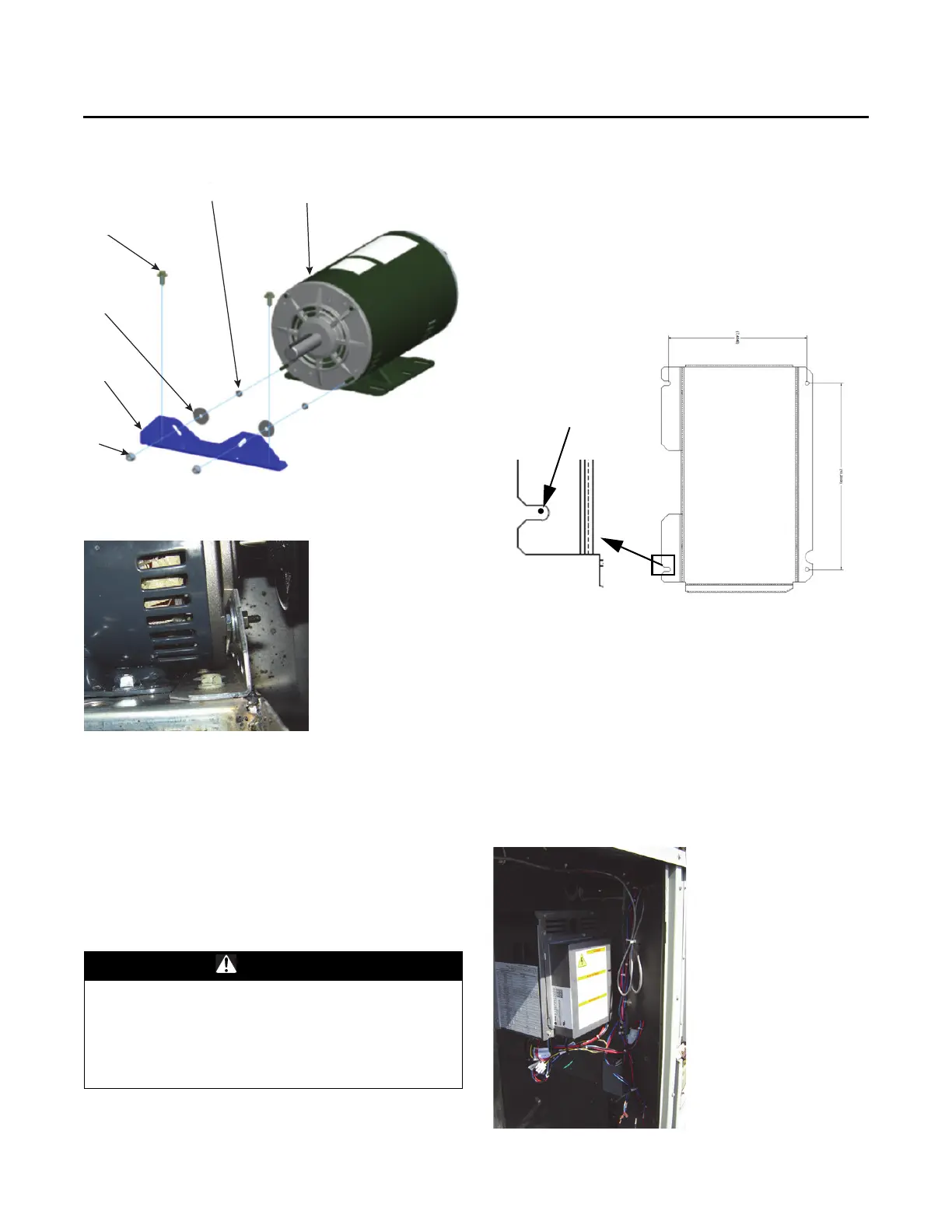
VFD Assembly Mounting
The VFD assembly is to be mounted on the interior wall in
the supply fan section using four sheet metal screws as
seen in Figure 6. In order to mount the assem
bly four 1/8th
in
ch holes will need to be drilled.
1. Use the paper template provid
ed to
mark the locations
of the four holes to be drilled. Note the location of the
temperature sensor for some gas heat units as the
wiring will need to reach around the drive assembly
after it is installed.
2. After locating and drilling the four holes, screw in two
of the sheet metal screws
in the left two holes so that
a small gap still remains between the bottom of the
screw head and the sheet metal wall.
3. Slide the left side of the drive assembly
that has slots
for m
ounting instead of holes on to the screws that are
part way screwed in. Holding the drive in place, screw
the two screws on the left side the rest of the way
down.
4. Screw in the two screws on the
right side of the drive
assembly.
Figure 3. Vibration bracket installation
Figure 4. 3 or 5 HP vibration bracket installed
WARNING
Hazardous Voltage!
Failure to disconnect power before servicing could
result in death or serious injury. Disconnect all electric
power, including remote disconnects before servicing.
Follow proper lockout/tagout procedures to ensure the
power can not be inadvertently energized.
Figure 5.
Figure 6. Field installed VFD assembly
Orient template as shown.
Marks for holes on left
side should be fully
into slots for holes
drilled on the right
side to line up
correctly.