PART-SVN227B-EN 7
Installation
Inverter Duty Motor and Vibration
Reduction Bracket
1. Remove the supply fan drive belt.
2. Unbolt and remove the existing motor. Remove the
drive
sheave from the motor shaft.
Note: As the dr
ive sheav
e is a common component to
replace due to wear and a different sheave is not
needed when upgrading to SZVAV or Multispeed, a
new sheave is not included as part of the upgrade
program. Sheaves are available through Trane
Supply or your Trane or American Standard parts
distributor.
3. Affix the sheave to the shaft
of the inverter duty motor.
A new shaft key is provided with the inverter duty
motor.
4. A new wiring harness to connect the motor to the VFD
is provided and will need
to be connected to the motor.
The gauge of the wire in the motor to drive harness
might be smaller than the wires that the existing motor
was using, this is in line with the current production
design.
Note: The m
otors used in the upgrade are dual voltage. If
the unit that is being upgraded is not 460V the
voltage plug on the back of the motor will need to
be taken out, rotated 180° and reinserted.
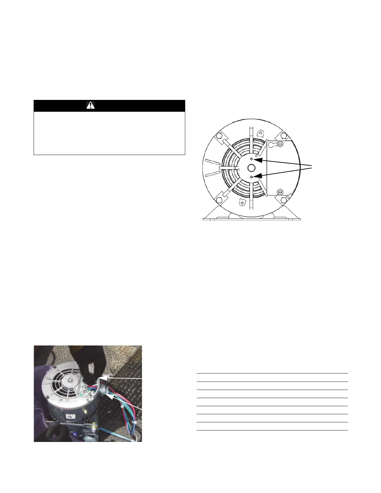
5. For additional motor bearing protection, a motor shaft
grounding ring is provided. Before installing the
motor, follow a, b, and c below to install the grounding
ring.
a. Remove the two screws from th
e back of the motor
as shown in Figure 2.
b. Slide the grounding ring over the end of the shaft
an
d ali
gn the holes in the ring with the holes that the
screws were in.
c. Using the screws and washers provided wi
th the
grounding ring secure the ring to the motor.
6. Install the inverter duty motor into
the unit.
7. Determine the location of the holes used to hold the
vibration bracket onto the motor mounting panel.
a. Dry fit the bracket according to Figure 3.
b. Use a marker to mark the lo
cation to
drill the holes
for the screws that will hold the bracket to the motor
mounting panel.
8. Drill the holes that were marked
using the 1/
8 inch drill
bit provided.
9. Install the vibration dampening bracket. See Fi
gure 3
for details.
WARNING
Hazardous Voltage!
Failure to disconnect power before servicing could
result in death or serious injury. Disconnect all electric
power, including remote disconnects before servicing.
Follow proper lockout/tagout procedures to ensure the
power can not be inadvertently energized.
Figure 1. Inverter duty motor
Voltage Plug
Reuse wire
collar from
motor that
was removed
Figure 2. Back side of inverter duty motor
Table 3.
Balloon Part
1 Inverter Duty Motor
2 Vibration Reduction Bracket
3 Screw, 1/4-14 X 0.625 (X25240209030)
4
(a)
(a) The torque applied to the nuts on the end of the extended bolts is to
be as follows:
18–25 in·lb (~2 ft·lb) for 3 and 5 HP motors
Nut, 10-32 Hex Lock (X28022600000)
5
(b)
(b)Use 1 washer on each bolt for 3 and 5 HP motors.
Washer, 0.328 ID X 2.00 OD (X22050242010)
6 Nut (attached by motor supplier)