Installation
12 PART-SVN227B-EN
Control Panel
1. Connect the ends of the 600B and 601B to VRR
terminals 2 and 4 as shown in Figure 15, p. 12.
a. For multispeed applications conne
ct wires 603B
and 604B to VSR
terminals 5 and 6 as shown in
Figure 15, p. 12.
b. For SZVAV conversions, connect pl
ug P11 (wires
604D and 607B) to the J11 pins on the RTOM
module.
2. Connect the end of wire 64A that was connected to the
supply fan
motor contactor to VRR-1 along with w
ire
64B. (Wire 64B only applies to electric heat/cooling
only units.)
3. Remove wire 36W (one end is curr
ently connected to
TNS1); it is re
placed by 36CC which is included with the
wiring kit. Connect one end of wire 36CC to VRR
terminal 3 and the other end to the GTB.
4. F
or Multispeed conversions, take wire 36CD (suppli
ed
in wiring kit) and connect one end to terminal 3 of the
VSR and the other end to the GTB. Also, for Multispeed
conversions connect the pl
ug that jumps RTRM P9-1 to
RTRM P9-2 to the RTRM board as shown in connection
diagram 01860036.
5. F
or Multispeed conversions, connect wire 608A to
terminal 1
of the VSR. Land the other end of the 608A
on plug P2, hole 5. P2 connects to the RTRM module at
J2. To attach wire 608A to pl
ug P2, slide the press fitting
into hole 5 of P2. This connection is shown on diagram
01860036. Use this diagram to find the correct hole
location on fitting P2.
6. For SZVAV conversions take the end of wire 36CE that
has th
e 7 pin
plug and connect it to the RTOM J12
location and plug the other end on to the GTB.
7. For gas heat units connect the end of wire 36AS that
was
connected to th
e supply fan contactor to the GTB.
For electric heat units connect the end of wire 36C that
was connected to the supply fan contactor to the GTB.
8. Connect Wire 36A to the GTB. In production
M
ult
ispeed/SZVAV units this wire is labeled as 36CF as
seen in Table 5, p. 10.
Note: Wire 36CF is i
ncluded in the wiring kit as a
substitute for wire 36A however, replacement is
not necessary.
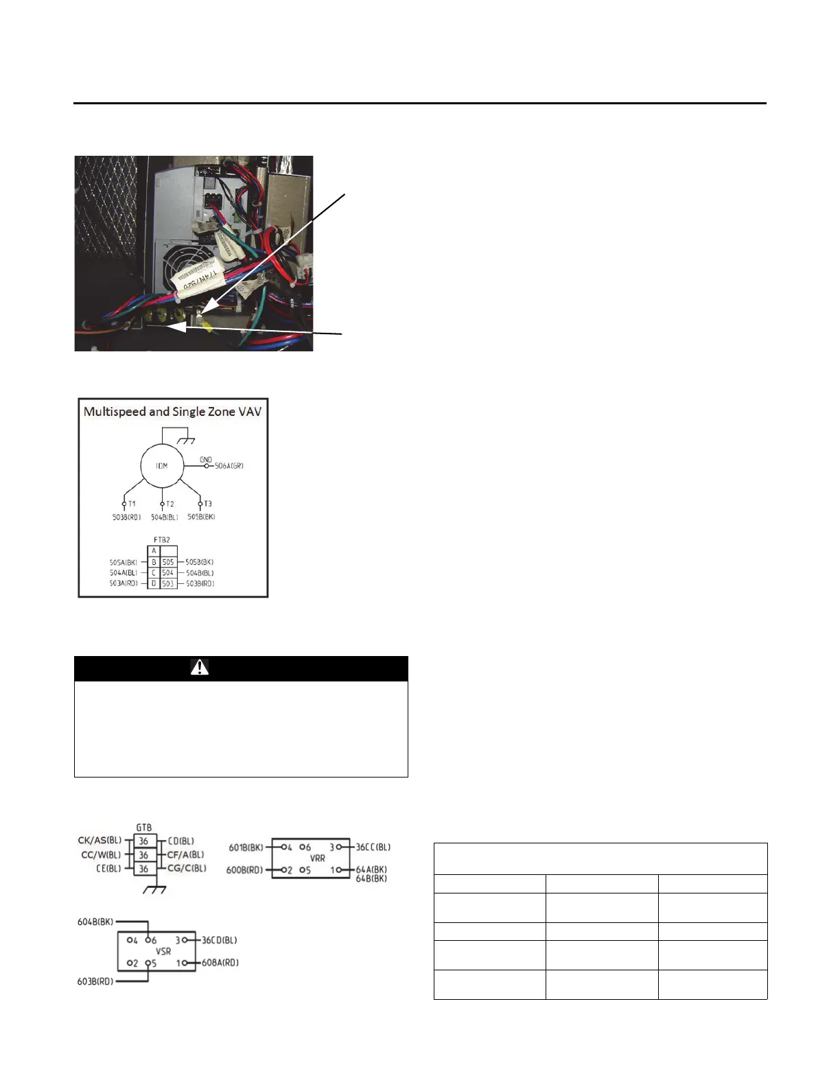
Figure 13. Motor to drive connections
Figure 14. Motor to drive schematic
WARNING
Hazardous Voltage!
Failure to disconnect power before servicing could
result in death or serious injury. Disconnect all electric
power, including remote disconnects before servicing.
Follow proper lockout/tagout procedures to ensure the
power can not be inadvertently energized.
Figure 15. GTB, VRR, and VSR wire connections
Table 6. Wire number differences
Wire Number Changes, Multispeed/SZVAV vs Constant
Volume
Multispeed/SZVAV Constant Volume Notes
36CC 36W
Wire 36CC is included
in wir
ing package
36CF 36A
36CG 36C
Wire 36CG is used
with elec
tric heat
36CK 36AS
Wire 36CK is used
with ga
s heat