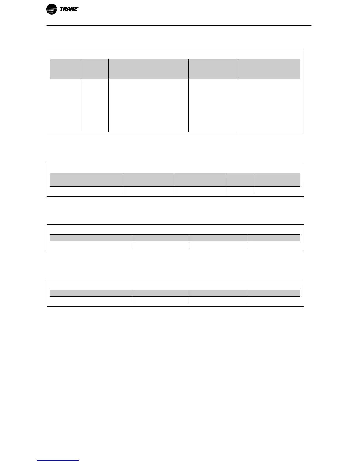
Digital Inputs - Terminal X30/1-4
Parameters for set-up: 5-16, 5-17 and 5-18
Number of
digital in-
puts
Voltage
level
Voltage levels Tolerance Max. Input impedance
3 0-24 V DC PNP type:
Common = 0 V
Logic “0”: Input < 5 V DC
Logic “0”: Input > 10 V DC
NPN type:
Common = 24 V
Logic “0”: Input > 19 V DC
Logic “0”: Input < 14 V DC
± 28 V continuous
± 37 V in minimum
10 sec.
Approx. 5 k ohm
Analog Voltage Inputs - Terminal X30/10-12
Parameters for set-up: 6-3*, 6-4* and 16-76
Number of analog voltage in-
puts
Standardized input
signal
Tolerance Resolu-
tion
Max. Input impe-
dance
2 0-10 V DC ± 20 V continuously 10 bits Approx. 5 K ohm
Digital Outputs - Terminal X30/5-7
Parameters for set-up: 5-32 and 5-33
Number of digital outputs Output level Tolerance Max.impedance
2 0 or 24 V DC ± 4 V ≥ 600 ohm
Analog Outputs - Terminal X30/5+8
Parameters for set-up: 6-6* and 16-77
Number of analog outputs Output signal level Tolerance Max.impedance
1 0/4 - 20 mA ± 0.1 mA < 500 ohm
4 TR200 Series VFD General Purpose I/O Option Module MCB 101 Instruction