Galvanic Isolation in the MCB 101
Digital/analog inputs are galvanically isolated from other inputs/outputs on the MCB 101 and in the control card
of the frequency converter. Digital/analog outputs in the MCB 101 are galvanically isolated from other inputs/
outputs on the MCB 101, but not from these on the control card of the drive.
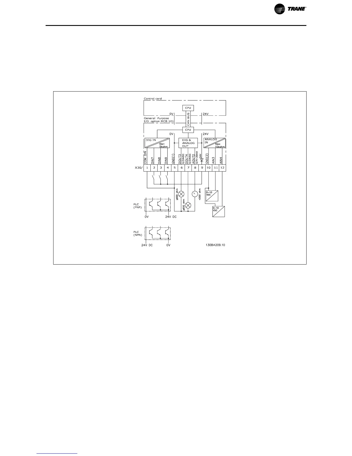
If the digital inputs 7, 8 or 9 are to be switched by use of the internal 24 V power supply (terminal 9) the connection
between terminal 1 and 5 which is illustrated in the drawing has to be established.
Illustration 1. 2: Principle Diagram
TR200 Series VFD General Purpose I/O Option Module MCB 101 Instruction 3