Wiring binary inputs
BMTX-SVN01C-EN 23
Wiring binary inputs
For binary input wiring, see Chapter 4, “BMTX BCU binary inputs.”
UCM wiring
For UCM wiring, see Chapter 5, “UCM communication link wiring and
topology.”
Connecting the main circuit board
The main circuit board is attached to a plastic frame. It is shipped
separately. The board can be kept in the office and programmed while the
back of the enclosure is mounted and the termination board, which is
attached to the back of the enclosure, is wired. After programming has
been completed, connect the circuit board to the termination board as
shown in the following procedure.
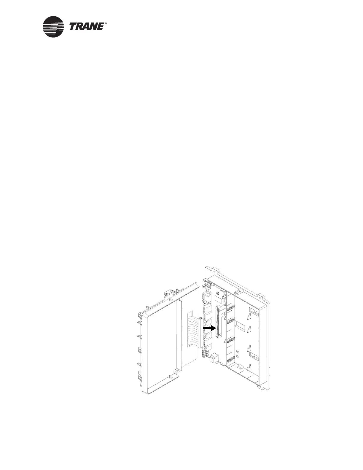
To connect the circuit board:
1. Verify that the 24 Vac power cable is not connected to the termination
board.
2. Hold the circuit board frame at a 90° angle to the back of the enclo-
sure, as shown in Figure 11.
Figure 11. Connecting the circuit board ribbon cable

 Loading...


