Description of UCM types
BMTX-SVN01C-EN 85
Voyager rooftop unit interface
Tracer Summit can monitor, control, and configure Voyager rooftop units.
The Voyager interface provides a Comm5, Comm4, or isolated Comm3
communication link between the BCU and each Voyager rooftop unit. For
specific information about the number of Voyagers allowed per BCU and
per communication link, refer to Table 5 on page 33.
Voyager rooftop units must have an LCI-V card installed to communica-
tion on a Comm5 link. Voyager rooftop units must have a TCI-3 module
installed to communicate on either an isolated Comm3 link or on Comm4
link. To configure The TCI-3 for isolated Comm3, the TCI-3 daughter
board must be rotated clockwise 90° from the position used for Comm4, so
that “Isolated Comm3” is at the bottom. Refer to the Trane Communica-
tion Interface (TCI-3) installation, operation, and maintenance literature
for more information on configuring the TCI-3.
Wiring requirements
To establish communication between the TCI-3 and the BMTX BCU, refer
to the specifications on wire type, topology, and wiring procedures in
“Comm3/Comm4 wiring” on page 35. Attach the communication link wire
to the TB1 SERIAL COMM (+) and (-) terminals on the TCI-3 board.
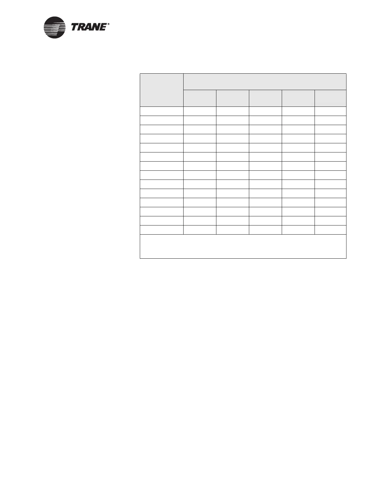
18 on OFF on on OFF
19 OFF OFF on on OFF
20 on on OFF on OFF
21 OFF on OFF on OFF
22 on OFF OFF on OFF
23 OFF OFF OFF on OFF
24 on on on OFF OFF
25 OFF on on OFF OFF
26 on OFF on OFF OFF
27 OFF OFF on OFF OFF
28 on on OFF OFF OFF
29 OFF on OFF OFF OFF
30 on OFF OFF OFF OFF
31 OFF OFF OFF OFF OFF
Note:
• DIP switches 6 and 7 are not used. Set them to the On position.
• DIP switch 8 is the Setup/Normal switch. Set it to the On/Normal position.
Table 23. VAV wireless receiver address settings (Continued)
UCM address
VAV wireless receiver DIP switch settings
DIP 1 DIP 2 DIP 3 DIP 4 DIP 5

 Loading...


