106 CNT-SVX17G-EN
Appendix D: Reheat Actuation Schedule Tables
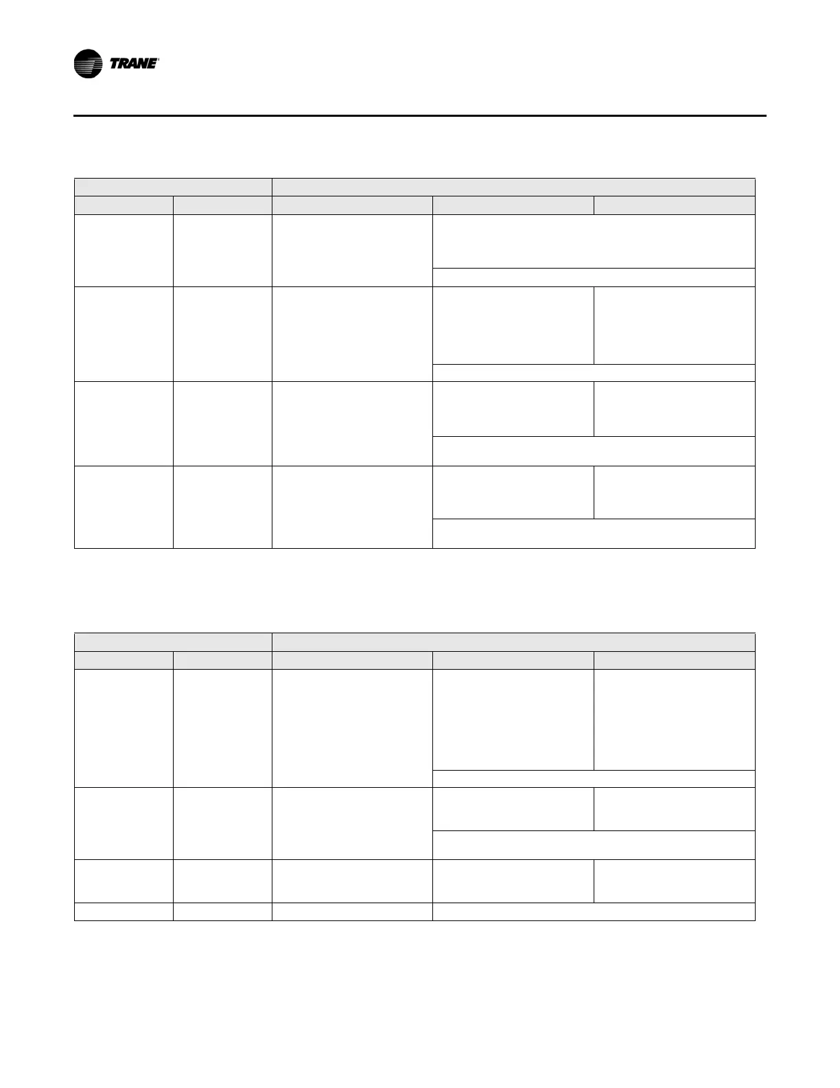
Fan priority
Modulating hot
water
Parallel fan
Remote PI capacity loop
Remote modulating valve capacity = Total capacity
Remote valve controls total capacity from 0% to 100%
Valve drive incrementally open/closed
Total capacity is limited by communicated auxiliary heat enable.
Fan +
PWM Electric
(one-stage)
priority
On/Off electric
(1 stage)
Parallel fan
Local PI capacity loop
Local heat capacity = 1/2 total
cap
a
city
Local heat controls capacity
fro
m
0% to 50%
PWM output
Remote capacity
Remote heat capacity = 1/2
total capacit
y
On: total capacity 100%
Off: t
otal capacity 50%
Total capacity is limited by communicated auxiliary heat enable.
Fan +
On/Off Electric
(one-stage)
priority
On/Off electric
(1 stage)
Parallel fan
Local thermostatic
On: Zt < HSP – 1°F (0.56°C)
Off: Zt
HSP – 0.5°F (0.28°C)
R
emote thermostatic
On: Zt < HSP – 2°F (1.11°C)
Off: Zt HSP – 1.5°F (0.83°C)
Each stage represents an equal percentage of total capacity.
To
tal capacity is limited by communicated auxiliary heat enable.
Fan +
On/Off hot water
(one-stage)
priority
On/Off hot water
(1 stage)
Parallel fan
Local thermostatic
On: Zt < HSP – 1°F (0.56°C)
Off: Zt
HSP – 0.5°F (0.28°C)
R
emote thermostatic
On: Zt < HSP – 2°F (1.11°C)
Off: Zt HSP – 1.5°F (0.83°C)
Each stage represents an equal percentage of total capacity.
To
tal capacity is limited by communicated auxiliary heat enable.
Table 71. Local and remote heat with remote heat priority and parallel fan present
Configuration Method of control
Local Remote Stage 1
a
Stage 2 Stage 3
Fan +
PWM Electric
(one-stage)
On/Off Electric
(one-stage)
priority
Fan
Remote capacity or
thermostatic
R
emote heat capacity = 1/2
total cap
acity
On: total capacity 50% or
Zt
< HSP – 0.5°F
Off: total capacity
0% or Zt
HSP +
0.5°F
Local PI capacity loop
Local heat capacity = 1/2 total
capa
city
Local heat controls capacity
from
50% to 100%
PWM output
Total capacity is limited by communicated auxiliary heat enable.
Fan +
On/Off Electric
(one-stage)
On/Off Electric
(one-stage)
priority
Fan
Remote thermostatic
On: Zt < HSP – 1°F (0.56°C)
Off: Zt
HSP – 0.5°F (0.28°C)
Loc
al thermostatic
On: Zt < HSP – 2°F (1.11°C)
Off: Zt HSP – 1.5°F (0.83°C)
Each stage represents an equal percentage of total capacity.
To
tal capacity is limited by communicated auxiliary heat enable.
Fan +
On/Off hot water
(one-stage)
On/Off hot water
(one-stage)
priority
Fan
Remote thermostatic
On: Zt < HSP – 1°F (0.56°C)
Off: Zt HSP – 0.5°F (0.28°C)
Loc
al thermostatic
On: Zt < HSP – 2°F (1.11°C)
Off: Zt HSP – 1.5°F (0.83°C)
Total capacity is limited by communicated auxiliary heat enable.
a. For more information on fan operation, see “Fan Control,” p. 64.
Abbreviations: Zt = Zone temperature; HSP = Heating setpoint
Table 70. Local and remote heat with local heat priority and parallel fan present (continued)
Configuration Method of control
Local Remote Stage 1
a
Stage 2 Stage 3
a. For more information on fan operation, see “Fan Control,” p. 64.
Abbreviations: Zt = Zone temperature; HSP = Heating setpoint

 Loading...


