24 CNT-SVX17G-EN
Sequence of Operations
This chapter provides information concerning the sequence of operation of the Tracer® VV550/
VV551 controllers. Topics consist of:
• Control modes;
• Control sequences;
• Occupancy;
• Space temperature control;
• Ventilation flow control;
• Flow tracking control;
• Stand-alone control;
• Air balance functions.
Control Modes
The Tracer VV550/VV551 controllers are factory configured for a variety of VAV unit types. The
controller supports three control modes: two temperature controls and one pressure control. Table
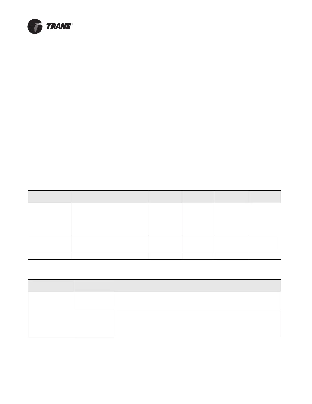
1 shows the basic unit type and control mode combinations, Table 2 describes the occupancy
modes for each control mode, and Table 3 shows the possible heat options.
Table 14.Options available depending on configured unit type and control algorithm
VAV unit type Control mode Air valve Fan Local heat
Remote
heat
Single duct Space temperature control (STC)
(space temperature sensor
requi
r
ed for normal operation, but
will run in construction mode
without a space temperature
sensor)
Required Optional Optional Optional
Single duct Ventilation flow control (VFC)
(discharge air tempe
r
ature sensor
required if reheat present)
Required None Optional None
Single duct Flow tracking (pressure) (FT) Required None None None
Table 15.Algorithm type and control sequence descriptions
Control mode
Occupancy
mode
Description
Space temperature
control
Occupied Contro
ller modulates the heating and cooling capacity to keep the space
temperature at the active space temperature setpoint. Applicable ventilation
and airflow setpoints are enforced. A space temperature sensor is required.
Unoccupied Controller enables or disables control to
keep the active space temperature
between the unoccupied heating and cooling setpoints. Ventilation requirements
are assumed to be zero. Minimum airflow setpoints are enforced when actively
cooling or heating, otherwise the air valve is closed. A space temperature sensor
is required.

 Loading...


