CNT-SVX17G-EN 25
Sequence of Operations
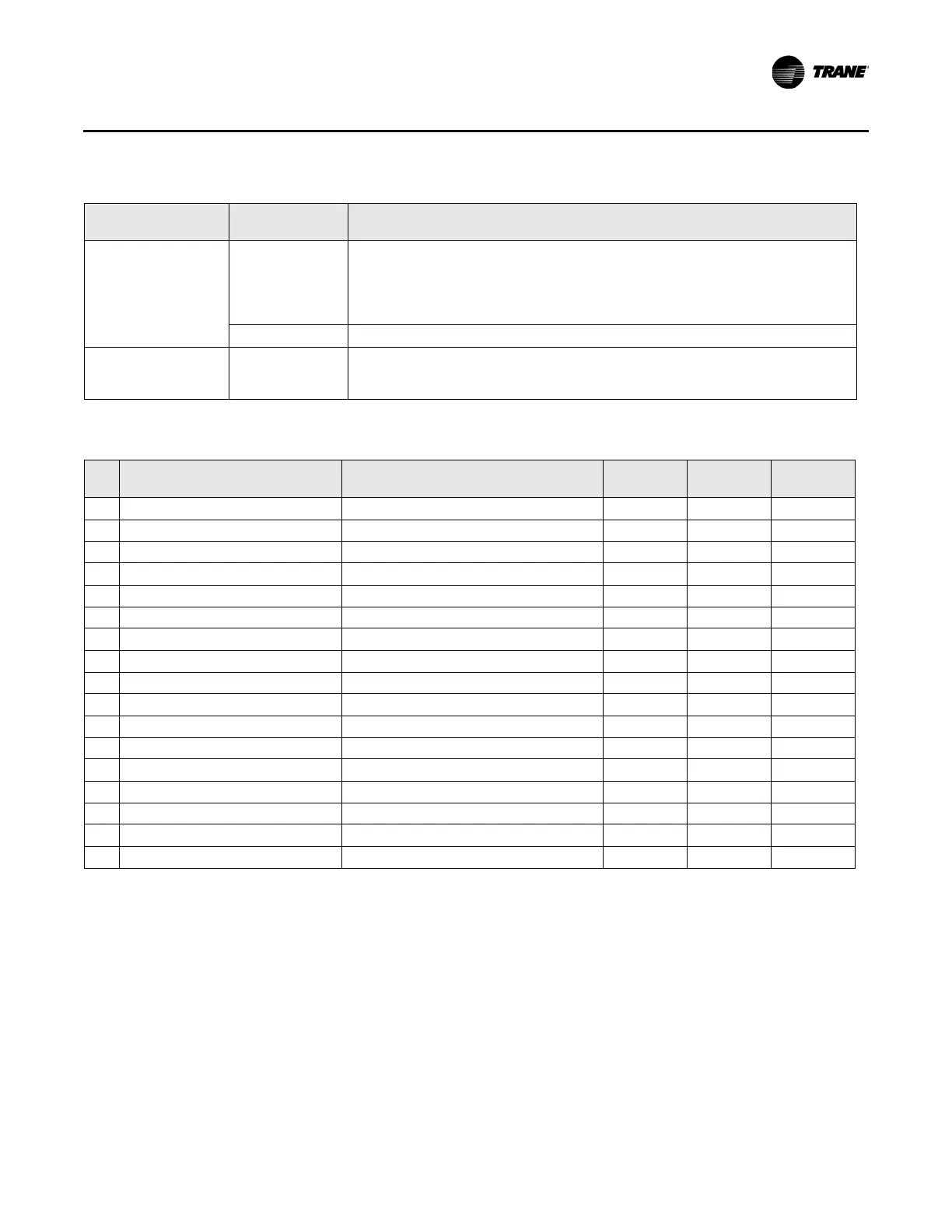
Ventilation flow
control
Occupied Controller controls to the active airflow setpoint and modulates the heating
capacity to keep the discharge air temperature at the active discharge air
temperature setpoint. A discharge air temperature sensor is required if reheat
is present. A space temperature sensor is not required. A diagnostic is generated
on a failure of the space temperature sensor input if it was ever valid.
Unoccupied Controller closes the air valve. All local heating capacity is disabled.
Airflow tracking
cont
rol
Occupied an
d
unoccupied
Controller supports one airflow tracking control algorithm. The controller
modulates the air valve to keep airflow at the calculated airflow setpoint. Neither
a space temperature nor a discharge air temperature sensor is required.
Table 16.Possible heat options
Local heat Remote heat Heat1 J9
Heat2
J10
Heat3
J11
1 No local heat
a
No remote heat
2 PWM electric (1 or 2 stages) No remote heat Local 1 Local 2 Fan
b
3 PWM electric (3 stages) No remote heat Local 1 Local 2 Local 3
4 Staged electric (1 or 2 stages)
a
No remote heat Local 1 Local 2 Fan
b
5 Staged electric (3 stages)
a
No remote heat Local 1 Local 2 Local 3
6 On/Off hot water (1 stage)
a
No remote heat Local 1 Fan
b
7 Modulating hot water
a, c
No remote heat Close Open Fan
b
8 No local heat Electric (1 stage) Remote 1 Fan
b
9 No local heat On/Off hot water (1 stage) Remote 1 Fan
b
10 No local heat Modulating hot water
c
Close Open Fan
b
11 PWM electric (1 stage) Electric (1 stage) Local 1 Remote 1 Fan
b
12 PWM electric (2 stages) Electric (1 stage) Local 1 Local 2 Remote 1
13 Staged electric (1 stage) Electric (1 stage) Local 1 Remote 1 Fan
b
14 Staged electric (2 stages) Electric (1 stage) Local 1 Local 2 Remote 1
15 On/Off hot water (1 stage) On/Off hot water (1 stage) Local 1 Remote 1 Fan
b
16 On/Off hot water (1 stage) Modulating hot water
c
Close Open Local 1
17 Modulating hot water
c
On/Off hot water (1 stage) Close Open Remote 1
Table 15.Algorithm type and control sequence descriptions (continued)
Control mode
Occupancy
mode
Description
a. Ventilation flow control only supports these types of heat.
b. The fan is optional, none, serial, or parallel.
c. Modulating hot water, local or remote, is always on HEAT1 (J9 closed) and HEAT2 (J10 open).

 Loading...


