CNT-SVX17G-EN 85
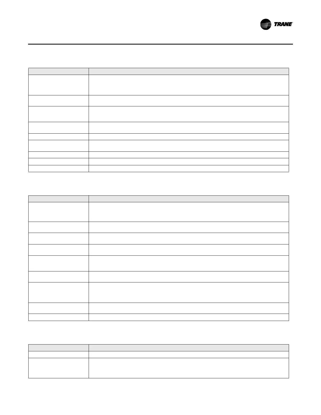
Troubleshooting
Manual output test
The controller includes a manual output test function you can use to verify output operation and associated
output wiring. However, based on the current step in the test sequence, the unit reheat may not be on. For
more information on manual output test, refer to sections “Manual Output Test,” p. 80 and “Manual Output
Tes t ,” p. 28.
Unit wiring
The wiring between the controller outputs and the fan relays and contacts must be present and correct for
no
rmal re
heat operation.
Low primary airflow
The unit must have sufficient primary airflow to energize t
h
e local electric reheat outputs. If the airflow never
reaches this level or falls below this level, the reheat is not energized. For more information on reheat
control, refer to “Reheat Control,” p. 45.
Primary air temperature
abo
ve reheat enable setpoint
The primary air temperature must be below the reheat enable setpoint before the reheat can be energized.
This prevents damage to the reheat coils due to excessive heat.
Invalid reheat enable setpoint Invalid reheat enable setpoint disa
bles local electric heat.
Invalid primary air
temperatur
e
Disables local electric heat when the system mode is heat or if system mode is auto with warm default
primary air temperature.
Fan override active Fan override Off with a fan present disables local electric reheat.
Auxiliary heat enable Communicated auxiliary heat enable is limiting reheat unit
capacity or disabling reheat completely.
Water valve override Water valve override, when in effect, controls outputs.
Table 57. Fan output does not energize
Probable cause Explanation
Power-up control wait
When power-up control wait is enabled (non-zero time), the controller remains Off until one of two
condi
tions occurs:
• The controller exits power-up control wait once it receives communicated information.
• The controller exits power-up control wait once the power-up control wait time expires.
Unoccupied operation
When the controller is in the
unoccupied mode, the fan is cycled between On and Off with capacity to
maintain zone temperature control.
Requested mode Off
You can communicate a desired operating mode (such as Off, heat, and cool) to the controller. When Off
is communi
cated to the controller, the unit controls the fan Off. There is no heating or cooling.
Diagnostic present
A specific list of diagnostics affects fan operation. For more information on controller diagnostics, refer to
Table 50, p. 81.
No power to the controller
If the controller does not have power, the unit fan does not operate. For the controller to operate normally,
it
must have an input voltage of 24 Vac. When the green LED is Off continuously, the controller does not
have sufficient power or has failed. For more information on green LED, refer to “Green Status LED,” p. 80.
Unit configuration
The controller must be properly configured based on the actual installed end devices and application. When
the un
it configuration does not match the actual end devices, the fan may not work correctly.
Manual output test
The controller includes a manual output test function you can use to verify output operation and associated
ou
tpu
t wiring. However, based on the current step in the test sequence, the unit fan may not be On. For
more information on manual output test, refer to sections “Manual Output Test,” p. 80 and “Manual Output
Tes t ,” p. 28.
Unit wiring
The wiring between the controller outputs and the fan relays and contacts must be present and correct for
normal fan op
eration.
Fan override Fan is overridden via communicated fan speed command.
Table 56. Reheat outputs do not energize (continued)
Probable cause Explanation
Table 58. Air valve and/or water valve stay open
Probable cause Explanation
Normal operation The controller opens and closes the valves to meet the unit capacity requirements.
Manual output test
The controller includes a manual output test function you can use to verify output operation and associated
ou
tpu
t wiring. However, based on the current step in the test sequence, the valve(s) may be open. For more
information on manual output test, refer to sections “Manual Output Test,” p. 80 and “Manual Output Test,”
p. 28.

 Loading...


